
onsemi (Ansemi)
Bild kan vara representation.
Se specifikationer för produktinformation.
Se specifikationer för produktinformation.
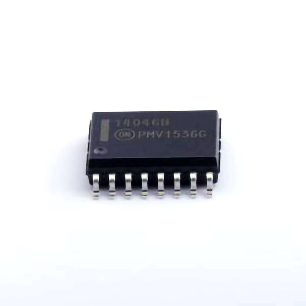
MC14046BDWR2G
phase locked loop
Artikelnummer
MC14046BDWR2G
Kategori
RTC/Clock Chip > Clock Generator/Frequency Synthesizer/PLL
Tillverkare/varumärke
onsemi (Ansemi)
Inkapsling
SOIC-16-300mil
Förpackning
taping
Antal paket
1000
Beskrivning
The MC14046B phase locked loop consists of two phase comparators, a voltage controlled oscillator (VCO), source follower and Zener diodes. These comparators have two common signal inputs PCAin and PCBin. The input PCAin can be used directly to couple large voltage signals, or indirectly (using a series capacitor) to couple small voltage signals. Self-biasing circuits condition small voltage signals in the linear region of the amplifier. Phase comparator 1 (dedicated OR gate) provides a digital error signal PC1out and maintains an intermediate frequency 90 phase shift between the PCAin and PCBin signals (both at 50% duty cycle). Phase comparator 2 (with leading-edge sensing logic) provides digital error signals PC2out and LD and maintains a 0-phase shift between the PCAin and PCBin signals (duty cycle is not important). This linear VCO produces an output signal VCOout whose frequency is determined by the voltage at the input VCOin and the capacitors and resistors connected to pins C1A, C1B, R1 and R2. For situations that require a VCOin flare that cannot tolerate loads, use a source follower with an external resistor to output SFout. The inhibit input, Inh, disables the VCO and source follower when high to minimize standby power consumption. Zener diodes can be used for power regulation. Applications include frequency modulation (FM) and FSK modulation and demodulation, frequency synthesis and multiplication, frequency identification, tone decoding, data synchronization and conditioning, voltage-to-frequency conversion, and motor speed control.
Begäran om begäran
Fyll i alla obligatoriska fält och klicka på " Skicka " kommer vi att kontakta dig om 12 timmar via e-post. Om du har problem, vänligen lämna meddelanden eller e-post till [email protected], vi kommer att svara så snart som möjligt.
I lager 86369 PCS
Kontaktinformation
Relaterade produkter

Nyckelord av MC14046BDWR2G
MC14046BDWR2G Elektroniska komponenter
MC14046BDWR2G Försäljning
MC14046BDWR2G Leverantör
MC14046BDWR2G Distributör
MC14046BDWR2G Datatabell
MC14046BDWR2G Foton
MC14046BDWR2G Pris
MC14046BDWR2G Erbjudande
MC14046BDWR2G Lägsta pris
MC14046BDWR2G Sök
MC14046BDWR2G Köp av
MC14046BDWR2G Chip