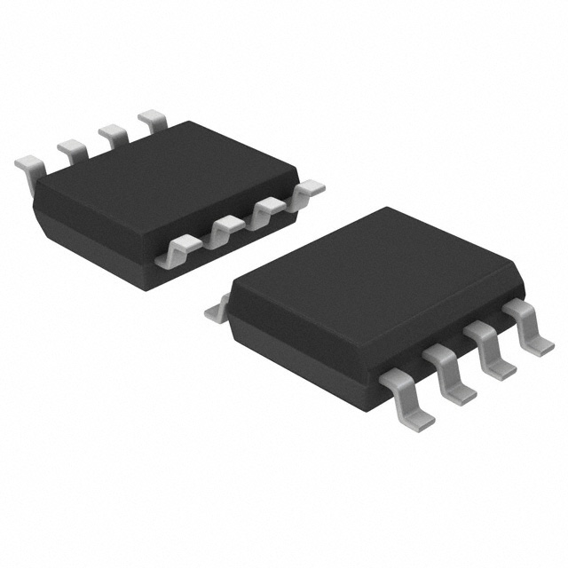
TL5002CDR
Product Overview
Category: Integrated Circuit (IC)
Use: Voltage Comparator
Characteristics: - High-speed voltage comparator - Low input offset voltage - Wide supply voltage range - Rail-to-rail output swing capability - Low quiescent current
Package: SOIC-8
Essence: The TL5002CDR is a high-performance voltage comparator designed for various applications that require precise and fast voltage comparisons.
Packaging/Quantity: The TL5002CDR is typically sold in reels of 2500 units.
Specifications
- Supply Voltage Range: 2.7V to 36V
- Input Offset Voltage: ±1mV (maximum)
- Input Bias Current: ±5nA (maximum)
- Response Time: 10ns (typical)
- Output Current: ±20mA
- Operating Temperature Range: -40°C to +125°C
Detailed Pin Configuration
The TL5002CDR features an 8-pin Small Outline Integrated Circuit (SOIC) package with the following pin configuration:
- VCC: Positive power supply
- IN+: Non-inverting input
- IN-: Inverting input
- GND: Ground reference
- OUT: Output
- NC: No connection
- NC: No connection
- VCC-: Negative power supply
Functional Features
- High-speed operation allows for quick voltage comparisons.
- Rail-to-rail output swing capability ensures accurate output signals even at extreme voltage levels.
- Low input offset voltage minimizes errors in voltage comparisons.
- Wide supply voltage range enables compatibility with various power sources.
- Low quiescent current reduces power consumption.
Advantages and Disadvantages
Advantages: - Fast response time - Wide operating temperature range - Low power consumption - Accurate voltage comparisons
Disadvantages: - Limited number of pins for additional functionalities - Not suitable for applications requiring high output current
Working Principles
The TL5002CDR operates as a voltage comparator by comparing the voltages at its non-inverting (IN+) and inverting (IN-) inputs. When the voltage at IN+ is higher than the voltage at IN-, the output (OUT) switches to a high state. Conversely, when the voltage at IN- is higher, the output switches to a low state. This behavior allows the TL5002CDR to determine the relationship between two input voltages accurately.
Detailed Application Field Plans
The TL5002CDR finds applications in various fields, including but not limited to: 1. Battery management systems 2. Power supply monitoring 3. Signal conditioning circuits 4. Motor control systems 5. Audio amplifiers
Detailed and Complete Alternative Models
- LM339: Quad voltage comparator with similar characteristics and pin configuration.
- LM311: High-speed voltage comparator with differential inputs.
- MAX9025: Ultra-low-power voltage comparator with rail-to-rail outputs.
These alternative models offer similar functionality to the TL5002CDR and can be considered as substitutes based on specific application requirements.
In conclusion, the TL5002CDR is a high-performance voltage comparator IC that offers fast response time, wide supply voltage range, and accurate voltage comparisons. Its compact SOIC-8 package makes it suitable for various applications in different fields. However, it has limitations in terms of pin count and output current capability. Engineers can consider alternative models such as LM339, LM311, or MAX9025 based on their specific needs.
Lista 10 Vanliga frågor och svar relaterade till tillämpningen av TL5002CDR i tekniska lösningar
Sure! Here are 10 common questions and answers related to the application of TL5002CDR in technical solutions:
Q: What is TL5002CDR? A: TL5002CDR is a voltage supervisor and reset IC that monitors the power supply voltage and provides a reset signal to the microcontroller or other digital devices.
Q: What is the operating voltage range of TL5002CDR? A: The operating voltage range of TL5002CDR is typically between 1.8V and 5.5V.
Q: How does TL5002CDR provide a reset signal? A: TL5002CDR monitors the power supply voltage and asserts the reset signal when the voltage drops below a certain threshold.
Q: Can TL5002CDR be used with both positive and negative voltage supplies? A: No, TL5002CDR is designed for use with positive voltage supplies only.
Q: What is the typical reset threshold voltage of TL5002CDR? A: The typical reset threshold voltage of TL5002CDR is 2.93V.
Q: Can TL5002CDR be used in battery-powered applications? A: Yes, TL5002CDR can be used in battery-powered applications as it has a low quiescent current consumption.
Q: Does TL5002CDR have any built-in delay for the reset signal? A: Yes, TL5002CDR has a fixed delay of approximately 200ms to ensure stable power supply before releasing the reset signal.
Q: Can TL5002CDR be used in automotive applications? A: Yes, TL5002CDR is suitable for automotive applications as it can withstand automotive voltage transients and has a wide operating temperature range.
Q: What is the package type of TL5002CDR? A: TL5002CDR is available in an 8-pin SOIC (Small Outline Integrated Circuit) package.
Q: Are there any application notes or reference designs available for TL5002CDR? A: Yes, Texas Instruments provides application notes and reference designs that can help in implementing TL5002CDR in various technical solutions.
Please note that the answers provided here are general and may vary depending on the specific datasheet and manufacturer's recommendations for TL5002CDR.


