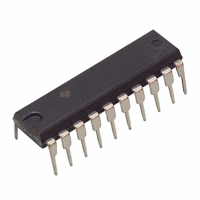
SN74LS697N
Product Overview
Category
SN74LS697N belongs to the category of integrated circuits (ICs).
Use
This IC is commonly used in digital electronics for various applications such as counters, shift registers, and frequency dividers.
Characteristics
- High-speed operation
- Low power consumption
- Wide operating voltage range
- TTL compatible inputs and outputs
Package
SN74LS697N is available in a 16-pin dual in-line package (DIP).
Essence
The essence of SN74LS697N lies in its ability to perform counting and shifting operations in digital circuits efficiently and accurately.
Packaging/Quantity
SN74LS697N is typically sold in reels or tubes containing multiple units. The exact quantity may vary depending on the supplier.
Specifications
- Supply Voltage: 4.75V to 5.25V
- Operating Temperature Range: -40°C to +85°C
- Maximum Clock Frequency: 25 MHz
- Number of Counting Stages: 4
- Number of Parallel Data Inputs: 4
- Number of Parallel Data Outputs: 4
Detailed Pin Configuration
- CLR (Clear) - Clear input
- CLK (Clock) - Clock input
- ENP (Enable Parallel) - Enable parallel data inputs
- ENT (Enable Trickle) - Enable trickle data inputs
- A0 (Parallel Data Input A0)
- A1 (Parallel Data Input A1)
- A2 (Parallel Data Input A2)
- A3 (Parallel Data Input A3)
- B0 (Parallel Data Input B0)
- B1 (Parallel Data Input B1)
- B2 (Parallel Data Input B2)
- B3 (Parallel Data Input B3)
- Q0 (Parallel Data Output Q0)
- Q1 (Parallel Data Output Q1)
- Q2 (Parallel Data Output Q2)
- Q3 (Parallel Data Output Q3)
Functional Features
- Counting: SN74LS697N can count up or down based on the clock input and control signals.
- Shifting: It can shift data in parallel or serially, depending on the configuration.
- Parallel Load: The IC allows loading of data in parallel when the enable signal is active.
Advantages and Disadvantages
Advantages
- High-speed operation enables efficient counting and shifting operations.
- Low power consumption makes it suitable for battery-powered devices.
- Wide operating voltage range provides flexibility in various applications.
- TTL compatibility ensures easy integration with other digital circuits.
Disadvantages
- Limited number of counting stages may restrict its use in complex applications.
- Lack of built-in error detection or correction mechanisms.
Working Principles
SN74LS697N operates based on the principles of synchronous digital logic. The clock input triggers the counting or shifting operations, while the control signals determine the direction and mode of operation. The parallel load feature allows loading of data into the IC when enabled.
Detailed Application Field Plans
SN74LS697N finds applications in various fields, including: - Digital frequency dividers - Industrial automation systems - Communication equipment - Automotive electronics - Consumer electronics
Detailed and Complete Alternative Models
Some alternative models that offer similar functionality to SN74LS697N are: - CD40193 - 74HC597 - 74F169
These alternatives may have different specifications and pin configurations, so it is important to refer to their respective datasheets for detailed information.
Word count: 443 words
Lista 10 Vanliga frågor och svar relaterade till tillämpningen av SN74LS697N i tekniska lösningar
Sure! Here are 10 common questions and answers related to the application of SN74LS697N in technical solutions:
Q: What is SN74LS697N? A: SN74LS697N is a 4-bit binary up/down counter with parallel load, designed for use in various digital applications.
Q: What is the maximum clock frequency supported by SN74LS697N? A: The maximum clock frequency supported by SN74LS697N is typically around 25 MHz.
Q: How many bits can SN74LS697N count up to? A: SN74LS697N is a 4-bit counter, so it can count up to 15 (1111 in binary).
Q: Can SN74LS697N count down as well? A: Yes, SN74LS697N can count both up and down based on the input signals provided.
Q: How does the parallel load feature work in SN74LS697N? A: The parallel load feature allows you to load a specific value into the counter by providing the desired binary input on the parallel load inputs.
Q: What is the purpose of the carry output in SN74LS697N? A: The carry output is used to cascade multiple counters together, enabling counting beyond 15.
Q: Can SN74LS697N be used in synchronous or asynchronous mode? A: SN74LS697N operates in synchronous mode, meaning that the outputs change simultaneously with the clock signal.
Q: What is the power supply voltage range for SN74LS697N? A: The recommended power supply voltage range for SN74LS697N is typically between 4.75V and 5.25V.
Q: What are the typical applications of SN74LS697N? A: SN74LS697N is commonly used in applications such as frequency dividers, digital counters, and general-purpose counting circuits.
Q: Are there any specific precautions to consider when using SN74LS697N? A: It is important to ensure that the power supply voltage does not exceed the specified range, and to follow proper grounding techniques to minimize noise interference. Additionally, care should be taken to avoid exceeding the maximum clock frequency to maintain reliable operation.


