

SN74AUC1G79DCKR
Product Overview
- Category: Integrated Circuit (IC)
- Use: Logic Gate
- Characteristics: Single Positive Edge-Triggered D-Type Flip-Flop
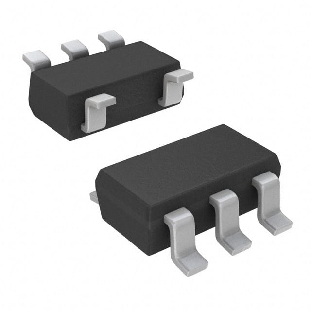
- Package: SC-70 (SOT-323)
- Essence: High-speed, low-power consumption flip-flop
- Packaging/Quantity: Tape and Reel, 3000 pieces per reel
Specifications
- Supply Voltage Range: 0.8V to 3.6V
- High-Speed Operation: 5.4 ns maximum propagation delay at 3.3V
- Low Power Consumption: 2.5 µA maximum ICC
- Operating Temperature Range: -40°C to +85°C
- Input/Output Compatibility: CMOS/TTL
Detailed Pin Configuration
The SN74AUC1G79DCKR has the following pin configuration:
```
| | -| CP |- Clock Pulse Input -| D |- Data Input -| Q |- Output -| GND|- Ground -| VCC|- Power Supply |____| ```
Functional Features
- Single positive edge-triggered D-type flip-flop
- High-speed operation for efficient data processing
- Low power consumption for energy efficiency
- Wide supply voltage range for versatile applications
- Compatible with both CMOS and TTL logic levels
- Compact package size for space-constrained designs
Advantages and Disadvantages
Advantages: - High-speed operation enables fast data processing - Low power consumption reduces energy usage - Wide supply voltage range allows for flexible power supply options - Compatibility with CMOS and TTL logic levels simplifies integration into existing systems - Compact package size saves board space in compact designs
Disadvantages: - Limited functionality as a single flip-flop - Not suitable for applications requiring multiple flip-flops or more complex logic functions
Working Principles
The SN74AUC1G79DCKR is a single positive edge-triggered D-type flip-flop. It stores and outputs a single bit of data based on the rising edge of the clock pulse input. The data input (D) determines the state of the flip-flop, which is then latched and reflected at the output (Q) when the clock pulse rises. The flip-flop operates within a specified supply voltage range and exhibits high-speed performance with low power consumption.
Detailed Application Field Plans
The SN74AUC1G79DCKR can be used in various applications, including but not limited to: - Digital communication systems - Microcontrollers and microprocessors - Data storage devices - Signal processing circuits - Industrial automation systems - Consumer electronics
Detailed and Complete Alternative Models
Some alternative models that offer similar functionality to the SN74AUC1G79DCKR include: - SN74AUC1G80DCKR: Single Positive Edge-Triggered D-Type Flip-Flop with Clear - SN74AUC1G81DCKR: Single Positive Edge-Triggered D-Type Flip-Flop with Set - SN74AUC1G82DCKR: Single Positive Edge-Triggered D-Type Flip-Flop with Reset
These alternative models provide additional features such as clear, set, or reset inputs, which can enhance the flexibility and functionality of the flip-flop circuit.
In conclusion, the SN74AUC1G79DCKR is a high-speed, low-power consumption single positive edge-triggered D-type flip-flop. It offers reliable data storage and retrieval capabilities, making it suitable for various digital logic applications.
Lista 10 Vanliga frågor och svar relaterade till tillämpningen av SN74AUC1G79DCKR i tekniska lösningar
Sure! Here are 10 common questions and answers related to the application of SN74AUC1G79DCKR in technical solutions:
Q1: What is SN74AUC1G79DCKR? A1: SN74AUC1G79DCKR is a single positive-edge-triggered D-type flip-flop with clear, designed for 1.65-V to 5.5-V VCC operation.
Q2: What is the purpose of SN74AUC1G79DCKR? A2: SN74AUC1G79DCKR is used to store and transfer data in digital circuits. It can be used in various applications such as counters, registers, and memory elements.
Q3: What is the operating voltage range of SN74AUC1G79DCKR? A3: SN74AUC1G79DCKR operates within a voltage range of 1.65V to 5.5V.
Q4: What is the maximum clock frequency supported by SN74AUC1G79DCKR? A4: SN74AUC1G79DCKR supports a maximum clock frequency of 200 MHz.
Q5: How many inputs and outputs does SN74AUC1G79DCKR have? A5: SN74AUC1G79DCKR has one data input (D), one clock input (CLK), one clear input (CLR), and one output (Q).
Q6: What is the propagation delay of SN74AUC1G79DCKR? A6: The propagation delay of SN74AUC1G79DCKR is typically around 2.8 ns.
Q7: Can SN74AUC1G79DCKR be used in battery-powered applications? A7: Yes, SN74AUC1G79DCKR can be used in battery-powered applications as it operates within a low voltage range of 1.65V to 5.5V.
Q8: Does SN74AUC1G79DCKR have any built-in protection features? A8: Yes, SN74AUC1G79DCKR has built-in ESD (Electrostatic Discharge) protection features to safeguard against electrostatic damage.
Q9: Can SN74AUC1G79DCKR be used in high-speed data transfer applications? A9: Yes, SN74AUC1G79DCKR can be used in high-speed data transfer applications as it supports a maximum clock frequency of 200 MHz.
Q10: What is the package type of SN74AUC1G79DCKR? A10: SN74AUC1G79DCKR is available in a small SOT-353 package, which is compact and suitable for space-constrained designs.
Please note that these answers are general and may vary depending on specific application requirements and datasheet specifications.