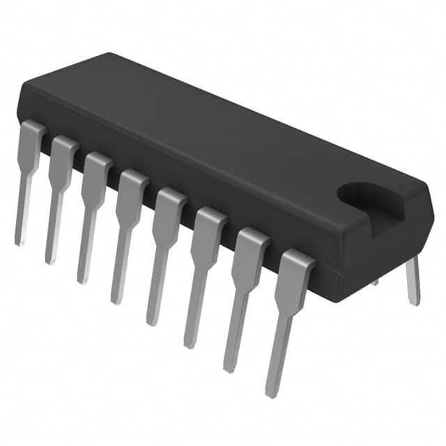
SN74ALS169BN
Product Overview
- Category: Integrated Circuit (IC)
- Use: Digital Counter
- Characteristics: High-speed, synchronous, 4-bit binary counter
- Package: DIP-16 (Dual In-line Package with 16 pins)
- Essence: Counting and sequencing digital signals
- Packaging/Quantity: Available in tubes of 25 or reels of 2,000 units
Specifications
- Supply Voltage Range: 4.5V to 5.5V
- Operating Temperature Range: -40°C to +85°C
- Maximum Clock Frequency: 50 MHz
- Maximum Counting Range: 15 (binary)
- Output Current: ±24 mA
- Propagation Delay: 10 ns (typical)
Detailed Pin Configuration
The SN74ALS169BN has a total of 16 pins, which are assigned specific functions:
- CP (Clock Pulse) - Input pin for clock signal
- P0-P3 (Parallel Data Inputs) - Four parallel data input pins
- MR (Master Reset) - Active low input for resetting the counter
- TC (Terminal Count) - Output pin indicating maximum count reached
- Q0-Q3 (Parallel Outputs) - Four parallel output pins
- GND (Ground) - Ground reference pin
- Q3' (Inverted Output) - Complementary output of Q3
- CE (Count Enable) - Active high input for enabling counting
- PE (Parallel Enable) - Active high input for parallel loading
- PEP (Parallel Enable Prime) - Active high input for parallel loading during the next clock cycle
- QA-QD (Serial Outputs) - Four serial output pins
- VCC (Positive Power Supply) - Positive power supply pin
Functional Features
- Synchronous operation: The counter advances on each clock pulse, ensuring accurate counting.
- Parallel and serial outputs: Provides flexibility in data retrieval.
- Master reset: Allows the counter to be reset to zero.
- Count enable: Enables or disables counting based on the input signal.
- Parallel loading: Allows presetting of the counter using parallel inputs.
Advantages and Disadvantages
Advantages: - High-speed operation - Synchronous counting ensures accuracy - Multiple output options for versatile applications - Easy integration into digital circuits
Disadvantages: - Limited counting range (up to 15) - Requires external clock signal for operation - Not suitable for applications requiring higher counting ranges
Working Principles
The SN74ALS169BN is a synchronous 4-bit binary counter. It counts up from 0 to 15 (binary) based on the clock pulses received at the CP pin. The counter can be reset to zero using the MR pin. The count enable (CE) input determines whether the counter advances or remains static. The parallel enable (PE) and parallel enable prime (PEP) inputs allow presetting of the counter using the parallel data inputs (P0-P3). The counter's current value can be retrieved through the parallel outputs (Q0-Q3) or the serial outputs (QA-QD).
Detailed Application Field Plans
The SN74ALS169BN finds applications in various fields, including:
- Digital electronics: Used as a basic building block for designing digital systems.
- Communication systems: Counting and sequencing signals in data transmission.
- Industrial automation: Monitoring and controlling processes that require counting operations.
- Automotive electronics: Speed measurement, odometer, and other automotive applications.
- Consumer electronics: Remote control devices, timers, and digital displays.
Detailed and Complete Alternative Models
- CD74HC163E: 4-bit synchronous binary counter with similar specifications and pin configuration.
- SN74LS169AN: 4-bit synchronous binary counter with lower power consumption.
- CD40161BE: 4-bit synchronous binary counter with additional features like asynchronous parallel load.
These alternative models offer similar functionality and can be used as replacements for the SN74ALS169BN in various applications.
Word count: 530 words
Lista 10 Vanliga frågor och svar relaterade till tillämpningen av SN74ALS169BN i tekniska lösningar
Sure! Here are 10 common questions and answers related to the application of SN74ALS169BN in technical solutions:
Q: What is SN74ALS169BN? A: SN74ALS169BN is a 4-bit synchronous binary up/down counter with parallel load.
Q: What is the operating voltage range for SN74ALS169BN? A: The operating voltage range for SN74ALS169BN is typically between 4.5V and 5.5V.
Q: Can SN74ALS169BN be used as a standalone counter? A: Yes, SN74ALS169BN can be used as a standalone counter without any additional components.
Q: How many clock inputs does SN74ALS169BN have? A: SN74ALS169BN has a single clock input (CLK) that controls the counting operation.
Q: Does SN74ALS169BN support both up-counting and down-counting? A: Yes, SN74ALS169BN supports both up-counting and down-counting based on the state of the UP/DOWN input.
Q: Can I load data into SN74ALS169BN while it's counting? A: No, SN74ALS169BN requires the LOAD input to be low in order to load data. It should not be changed during counting.
Q: What is the maximum frequency at which SN74ALS169BN can operate? A: The maximum clock frequency for SN74ALS169BN is typically around 50 MHz.
Q: How many output pins does SN74ALS169BN have? A: SN74ALS169BN has four output pins (Q0, Q1, Q2, Q3) that represent the binary count.
Q: Can I cascade multiple SN74ALS169BN counters to increase the number of bits? A: Yes, you can cascade multiple SN74ALS169BN counters to create larger count values.
Q: What are some typical applications for SN74ALS169BN? A: SN74ALS169BN is commonly used in applications such as frequency division, event counting, and general-purpose counting.
Please note that these answers are general and may vary depending on specific use cases and requirements.


