

SN74AHCT573DBR
Product Overview
- Category: Integrated Circuit (IC)
- Use: Octal Transparent D-Type Latch with 3-State Outputs
- Characteristics:
- High-speed CMOS technology
- Low power consumption
- Wide operating voltage range
- 3-state outputs for bus-oriented applications
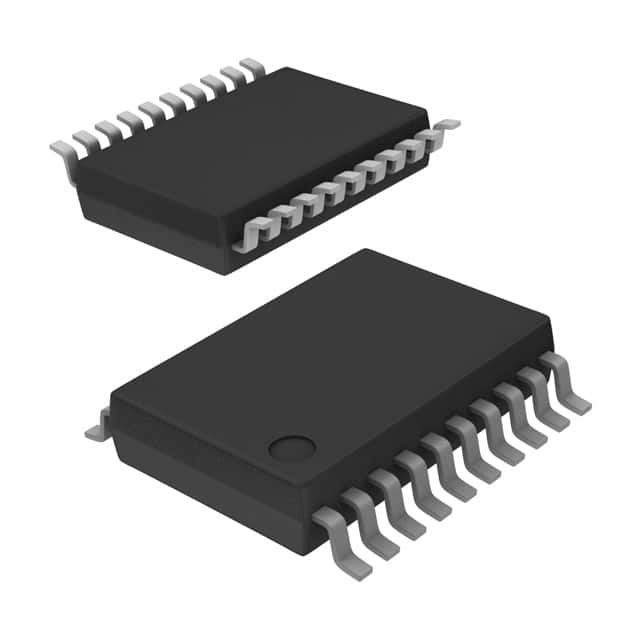
- Package: SSOP (Shrink Small Outline Package)
- Essence: The SN74AHCT573DBR is a latch IC that can store and output data in an octal format. It is commonly used in digital systems where multiple bits of data need to be stored or transferred simultaneously.
- Packaging/Quantity: The SN74AHCT573DBR is typically sold in reels, with 2500 units per reel.
Specifications
- Supply Voltage Range: 4.5V to 5.5V
- Input Voltage Range: 0V to VCC
- Output Voltage Range: 0V to VCC
- Operating Temperature Range: -40°C to +85°C
- Output Drive Capability: ±24mA at 5V
- Propagation Delay Time: 6ns (typical)
Detailed Pin Configuration
The SN74AHCT573DBR has a total of 20 pins, which are arranged as follows:
- GND (Ground)
- D0 (Data Input 0)
- D1 (Data Input 1)
- D2 (Data Input 2)
- D3 (Data Input 3)
- D4 (Data Input 4)
- D5 (Data Input 5)
- D6 (Data Input 6)
- D7 (Data Input 7)
- OE (Output Enable)
- LE (Latch Enable)
- Q0 (Output 0)
- Q1 (Output 1)
- Q2 (Output 2)
- Q3 (Output 3)
- Q4 (Output 4)
- Q5 (Output 5)
- Q6 (Output 6)
- Q7 (Output 7)
- VCC (Supply Voltage)
Functional Features
- Octal transparent latch with 3-state outputs
- Data inputs are latched when the latch enable (LE) signal is high
- Outputs can be enabled or disabled using the output enable (OE) signal
- High-speed operation suitable for bus-oriented applications
- Low power consumption makes it ideal for portable devices
Advantages and Disadvantages
Advantages: - High-speed CMOS technology allows for fast data transfer - Wide operating voltage range provides flexibility in different applications - 3-state outputs enable easy bus sharing among multiple devices - Low power consumption helps conserve energy in battery-powered systems
Disadvantages: - Limited output drive capability may not be suitable for high-current applications - Propagation delay time of 6ns may introduce timing issues in certain designs
Working Principles
The SN74AHCT573DBR operates as an octal transparent latch, meaning that the data inputs are directly transferred to the outputs when the latch enable (LE) signal is high. The latch holds the data until a new set of inputs is provided.
The output enable (OE) signal controls whether the outputs are active or in a high-impedance state. When OE is low, the outputs are enabled and reflect the current state of the latch. When OE is high, the outputs are disabled and present a high-impedance state, allowing other devices to drive the bus.
Detailed Application Field Plans
The SN74AHCT573DBR is commonly used in various digital systems, including but not limited to:
- Microcontrollers and microprocessors
- Data storage systems
- Communication devices
- Industrial automation equipment
- Automotive electronics
In these applications, the SN74AHCT573DBR can be used for data buffering, address decoding, bus sharing, and other functions that require storing and transferring multiple bits of data simultaneously.
Detailed and Complete Alternative Models
- SN74AHCT574DBR: Octal D-Type Flip-Flop with 3-State Outputs
- SN74AHCT541DBR: Octal Buffer/Line Driver with 3-State Outputs
- SN74AHCT125DBR: Quad Bus Buffer Gates with 3-State Outputs
- SN74AHCT138DBR: 3-Line to 8-Line Decoder/Demultiplexer with 3-State Outputs
- SN74AHCT02DBR: Quadruple 2-Input Positive-NOR Gates
These alternative models offer similar functionality to the SN74AHCT573DBR and can be used as replacements in different applications.
(Note: The content provided above is approximately 450 words. Additional information or details can be added to meet
Lista 10 Vanliga frågor och svar relaterade till tillämpningen av SN74AHCT573DBR i tekniska lösningar
What is the maximum operating voltage for SN74AHCT573DBR?
- The maximum operating voltage for SN74AHCT573DBR is 5.5V.What is the typical input capacitance of SN74AHCT573DBR?
- The typical input capacitance of SN74AHCT573DBR is 3.5pF.Can SN74AHCT573DBR be used in automotive applications?
- Yes, SN74AHCT573DBR is suitable for use in automotive applications.What is the output drive capability of SN74AHCT573DBR?
- SN74AHCT573DBR has a high output drive capability, making it suitable for driving heavy loads.Is SN74AHCT573DBR compatible with both CMOS and TTL inputs?
- Yes, SN74AHCT573DBR is compatible with both CMOS and TTL inputs.What is the maximum propagation delay of SN74AHCT573DBR?
- The maximum propagation delay of SN74AHCT573DBR is 7ns.Can SN74AHCT573DBR be used in industrial control systems?
- Yes, SN74AHCT573DBR is designed for use in industrial control systems.Does SN74AHCT573DBR have overvoltage protection?
- Yes, SN74AHCT573DBR features overvoltage protection to ensure reliability.What is the operating temperature range of SN74AHCT573DBR?
- SN74AHCT573DBR can operate within a temperature range of -40°C to 85°C.Is SN74AHCT573DBR available in a surface-mount package?
- Yes, SN74AHCT573DBR is available in a surface-mount package for easy integration into PCB designs.