

PCA9535PWG4
Product Overview
Category: Integrated Circuit (IC)
Use: The PCA9535PWG4 is a 16-bit I2C-bus and SMBus I/O expander optimized for dimming LEDs in applications such as backlight control, keypad illumination, and general-purpose output expansion.
Characteristics: - 16-bit remote bidirectional I/O port - Low standby current consumption of 1 µA (max) - 400 kHz Fast-mode I2C-bus interface - Internal power-on reset - Noise filter on SCL/SDA inputs - No glitch on power-up - Supports hot insertion - Active LOW open-drain interrupt output - Polarity inversion register - 25 mA sink/source capability per I/O - ESD protection exceeds JESD 22
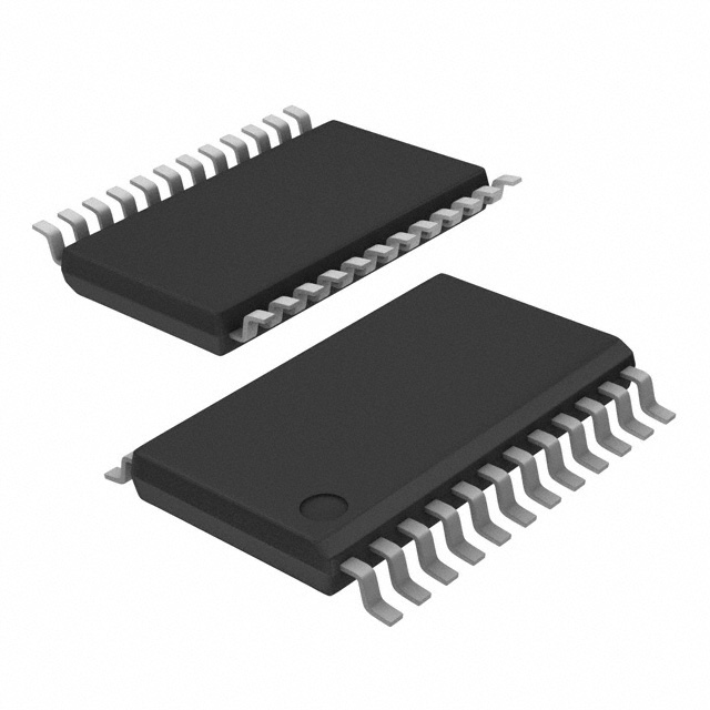
Package: TSSOP-24
Essence: The PCA9535PWG4 is an essential component for controlling LED brightness and expanding the number of available I/O ports in various electronic devices.
Packaging/Quantity: The PCA9535PWG4 is typically sold in reels or tubes containing 250 units.
Specifications
- Supply Voltage Range: 2.3 V to 5.5 V
- Input Voltage Range: GND to VDD
- Operating Temperature Range: -40°C to +85°C
- I2C-bus Frequency: 0 Hz to 400 kHz
Detailed Pin Configuration
The PCA9535PWG4 features a TSSOP-24 package with the following pin configuration:
| Pin Number | Pin Name | Description | |------------|----------|-------------| | 1 | A0 | Address input pin 0 | | 2 | A1 | Address input pin 1 | | 3 | A2 | Address input pin 2 | | 4 | P00 | I/O Port 0, Pin 0 | | 5 | P01 | I/O Port 0, Pin 1 | | 6 | P02 | I/O Port 0, Pin 2 | | 7 | P03 | I/O Port 0, Pin 3 | | 8 | P04 | I/O Port 0, Pin 4 | | 9 | P05 | I/O Port 0, Pin 5 | | 10 | P06 | I/O Port 0, Pin 6 | | 11 | P07 | I/O Port 0, Pin 7 | | 12 | INT | Interrupt Output | | 13 | SDA | I2C-bus Serial Data | | 14 | SCL | I2C-bus Serial Clock | | 15 | GND | Ground | | 16 | P17 | I/O Port 1, Pin 7 | | 17 | P16 | I/O Port 1, Pin 6 | | 18 | P15 | I/O Port 1, Pin 5 | | 19 | P14 | I/O Port 1, Pin 4 | | 20 | P13 | I/O Port 1, Pin 3 | | 21 | P12 | I/O Port 1, Pin 2 | | 22 | P11 | I/O Port 1, Pin 1 | | 23 | P10 | I/O Port 1, Pin 0 | | 24 | VDD | Supply Voltage |
Functional Features
The PCA9535PWG4 offers the following functional features:
16-bit Remote Bidirectional I/O Port: Provides 16 I/O pins that can be configured as either inputs or outputs.
Low Standby Current Consumption: Consumes only 1 µA (max) of current in standby mode, ensuring minimal power consumption.
Fast-mode I2C-bus Interface: Supports communication speeds up to 400 kHz, enabling efficient data transfer between the PCA9535PWG4 and the microcontroller.
Internal Power-on Reset: Automatically resets the device upon power-up, ensuring proper initialization.
Noise Filter on SCL/SDA Inputs: Filters out noise on the I2C-bus interface, enhancing signal integrity.
Hot Insertion Support: Allows the PCA9535PWG4 to be inserted or removed from a live system without causing any damage.
Active LOW Open-drain Interrupt Output: Generates an interrupt signal when a change is detected on any of the I/O pins.
Polarity Inversion Register: Allows individual inversion of the input/output port
Lista 10 Vanliga frågor och svar relaterade till tillämpningen av PCA9535PWG4 i tekniska lösningar
Sure! Here are 10 common questions and answers related to the application of PCA9535PWG4:
Q: What is PCA9535PWG4? A: PCA9535PWG4 is a 16-bit I/O expander with an I2C interface, which allows for easy expansion of GPIO (General Purpose Input/Output) pins in various technical solutions.
Q: How does PCA9535PWG4 communicate with a microcontroller? A: PCA9535PWG4 communicates with a microcontroller using the I2C protocol, which enables bidirectional communication between devices over a two-wire serial bus.
Q: What is the maximum number of PCA9535PWG4 devices that can be connected in a single I2C bus? A: The maximum number of PCA9535PWG4 devices that can be connected in a single I2C bus is determined by the address pins on the device, allowing up to 8 unique addresses.
Q: Can PCA9535PWG4 be used as both input and output pins? A: Yes, PCA9535PWG4 can be configured as either input or output pins individually. Each pin can be independently set as an input or output.
Q: What is the voltage range supported by PCA9535PWG4? A: PCA9535PWG4 supports a wide voltage range from 2.3V to 5.5V, making it compatible with various microcontrollers and systems.
Q: How much current can each output pin of PCA9535PWG4 sink or source? A: Each output pin of PCA9535PWG4 can sink or source up to 25mA of current, making it suitable for driving LEDs, relays, and other low-power devices.
Q: Can PCA9535PWG4 be used to control high-power devices? A: No, PCA9535PWG4 is not designed to directly control high-power devices. It is recommended to use external drivers or relays for controlling high-power loads.
Q: Does PCA9535PWG4 have built-in pull-up resistors? A: Yes, PCA9535PWG4 has built-in programmable pull-up resistors that can be enabled or disabled on each input pin individually.
Q: Can PCA9535PWG4 operate in a low-power mode? A: Yes, PCA9535PWG4 supports a low-power mode where it consumes minimal current, making it suitable for battery-powered applications.
Q: Are there any libraries or example codes available for PCA9535PWG4? A: Yes, many microcontroller platforms provide libraries and example codes for interfacing with PCA9535PWG4, making it easier to integrate into your technical solution.
Please note that these answers are general and may vary depending on the specific implementation and requirements of your technical solution.