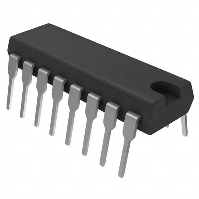
CD74HCT112E
Product Overview
- Category: Integrated Circuit
- Use: Logic Gate
- Characteristics: High-Speed, CMOS Technology
- Package: DIP (Dual In-line Package)
- Essence: Dual J-K Flip-Flop with Set and Reset
- Packaging/Quantity: Tube, 25 pieces per tube
Specifications
- Supply Voltage: 2V to 6V
- Logic Family: HCT
- Number of Pins: 16
- Operating Temperature Range: -40°C to +85°C
- Propagation Delay: 14 ns (typical)
- Output Current: ±4 mA
- Input Capacitance: 3.5 pF (typical)
Detailed Pin Configuration
- CLR (Clear Input 1)
- CLK (Clock Input 1)
- J (J Input 1)
- K (K Input 1)
- Q (Output 1)
- Q̅ (Complementary Output 1)
- GND (Ground)
- Q̅ (Complementary Output 2)
- Q (Output 2)
- K (K Input 2)
- J (J Input 2)
- CLK (Clock Input 2)
- CLR (Clear Input 2)
- VCC (Positive Supply Voltage)
- GND (Ground)
- VCC (Positive Supply Voltage)
Functional Features
The CD74HCT112E is a dual J-K flip-flop with set and reset functionality. It is designed using high-speed CMOS technology, making it suitable for applications requiring fast switching times. The flip-flop can operate within a wide supply voltage range of 2V to 6V, allowing flexibility in various electronic systems.
Advantages and Disadvantages
Advantages: - High-speed operation - Wide supply voltage range - Compact DIP package for easy integration - Set and reset functionality for versatile applications
Disadvantages: - Limited output current capacity - Relatively high input capacitance
Working Principles
The CD74HCT112E operates based on the J-K flip-flop principle. It has two independent flip-flops, each with J (data) and K (clock) inputs, as well as set and reset inputs. The outputs of the flip-flops provide both normal and complementary signals. The flip-flop can be clocked using the CLK input, and the state of the flip-flop can be cleared using the CLR input. The J and K inputs determine the next state of the flip-flop based on the current state and clock signal.
Detailed Application Field Plans
The CD74HCT112E is commonly used in digital systems where sequential logic operations are required. Some specific application areas include:
- Counters: The flip-flop can be used as a building block for designing counters that increment or decrement based on clock pulses.
- Registers: It can be utilized in register designs to store and transfer data within a digital system.
- State Machines: The flip-flop's ability to store and change states makes it suitable for implementing state machines in various applications.
- Clock Dividers: By utilizing the flip-flop's clock input, it can be employed to divide the frequency of an input clock signal.
Detailed and Complete Alternative Models
- SN74HCT112E: Similar dual J-K flip-flop with set and reset functionality, offered by Texas Instruments.
- MC74HCT112: Dual J-K flip-flop with set and reset, manufactured by ON Semiconductor.
- CD4013BE: Dual D-type flip-flop with set and reset, an alternative for different functionality requirements.
These alternative models provide similar functionality to the CD74HCT112E and can be considered based on specific design needs.
In conclusion, the CD74HCT112E is a high-speed CMOS integrated circuit belonging to the logic gate category. It offers dual J-K flip-flops with set and reset functionality, making it suitable for various digital applications. With its compact DIP package and wide supply voltage range, it provides flexibility in system integration. However, it has limitations in output current capacity and input capacitance. The detailed pin configuration, working principles, application field plans, and alternative models make it a versatile choice for sequential logic designs.
Lista 10 Vanliga frågor och svar relaterade till tillämpningen av CD74HCT112E i tekniska lösningar
Sure! Here are 10 common questions and answers related to the application of CD74HCT112E in technical solutions:
Q: What is CD74HCT112E? A: CD74HCT112E is a dual J-K flip-flop integrated circuit (IC) that can be used in various digital logic applications.
Q: What is the operating voltage range for CD74HCT112E? A: CD74HCT112E operates within a voltage range of 4.5V to 5.5V.
Q: What is the maximum clock frequency supported by CD74HCT112E? A: CD74HCT112E can support clock frequencies up to 25 MHz.
Q: How many flip-flops are there in CD74HCT112E? A: CD74HCT112E contains two independent J-K flip-flops.
Q: What is the output drive capability of CD74HCT112E? A: CD74HCT112E has a standard output drive capability of 4 mA.
Q: Can CD74HCT112E be used in both synchronous and asynchronous applications? A: Yes, CD74HCT112E can be used in both synchronous and asynchronous applications.
Q: What is the power dissipation of CD74HCT112E? A: The power dissipation of CD74HCT112E is typically around 20 mW.
Q: Does CD74HCT112E have any built-in protection features? A: Yes, CD74HCT112E has built-in protection against electrostatic discharge (ESD).
Q: What is the typical propagation delay of CD74HCT112E? A: The typical propagation delay of CD74HCT112E is around 15 ns.
Q: Can CD74HCT112E be used in high-speed applications? A: While CD74HCT112E can support clock frequencies up to 25 MHz, it may not be suitable for very high-speed applications where faster flip-flops are required.
Please note that these answers are general and may vary depending on the specific datasheet and manufacturer's specifications for CD74HCT112E.


