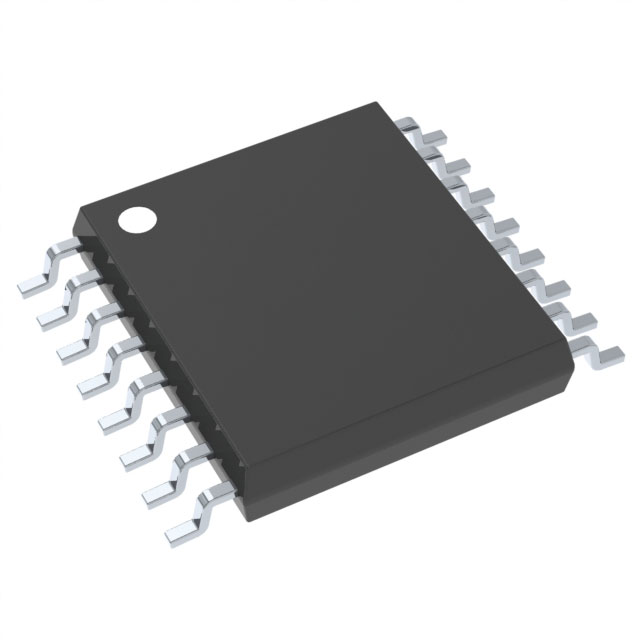
CD74HC4017PW
Product Overview
Category
CD74HC4017PW belongs to the category of integrated circuits (ICs).
Use
This product is commonly used in electronic devices for various applications, including digital counters, frequency dividers, and sequential control systems.
Characteristics
- High-speed operation
- Wide operating voltage range
- Low power consumption
- Schmitt trigger action on all inputs
- Balanced propagation delays
- Wide supply voltage range
Package
CD74HC4017PW is available in a small outline package (SOIC) with 16 pins.
Essence
The essence of CD74HC4017PW lies in its ability to provide a versatile and efficient solution for digital counting and sequential control tasks.
Packaging/Quantity
This product is typically packaged in reels or tubes, with each reel containing a specific quantity of CD74HC4017PW ICs.
Specifications
- Supply Voltage: 2V to 6V
- Input Voltage: 0V to VCC
- Output Voltage: 0V to VCC
- Operating Temperature Range: -40°C to +85°C
- Maximum Clock Frequency: 25 MHz
- Maximum Power Dissipation: 500 mW
Detailed Pin Configuration
- Clock (CLK)
- Reset (RST)
- Enable (EN)
- Data (D0)
- Data (D1)
- Data (D2)
- Data (D3)
- Data (D4)
- Data (D5)
- Data (D6)
- Data (D7)
- Data (D8)
- Data (D9)
- Data (D10)
- Data (D11)
- VCC (Power Supply)
Functional Features
- Decade counter with 10 decoded outputs
- Direct reset and enable inputs for easy control
- Schmitt trigger action on clock input for noise immunity
- Balanced propagation delays for synchronous operation
Advantages and Disadvantages
Advantages
- High-speed operation allows for efficient counting and control tasks.
- Wide operating voltage range provides flexibility in various applications.
- Low power consumption contributes to energy efficiency.
- Schmitt trigger action on all inputs ensures reliable performance.
- Balanced propagation delays enable synchronous operation.
Disadvantages
- Limited maximum clock frequency of 25 MHz may not be suitable for high-speed applications.
- Operating temperature range of -40°C to +85°C may restrict usage in extreme environments.
Working Principles
CD74HC4017PW operates as a decade counter, which means it can count from 0 to 9 and provide 10 decoded outputs. The clock input (CLK) triggers the counter to increment its count by one. The reset input (RST) resets the counter to zero, while the enable input (EN) controls the counting operation.
The data inputs (D0-D11) determine the initial count value when the counter is enabled. Each clock pulse increments the count, and the corresponding output is activated. When the count reaches 9, the next clock pulse resets the counter to zero.
Detailed Application Field Plans
CD74HC4017PW finds extensive application in various fields, including: 1. Digital frequency dividers 2. Sequential control systems 3. Electronic counters 4. Industrial automation 5. Robotics 6. Automotive electronics 7. Home appliances 8. Communication devices
Detailed and Complete Alternative Models
- CD4017BE: This model offers similar functionality but comes in a different package (DIP).
- CD74HCT4017E: This alternative provides compatibility with TTL logic levels.
- CD4022B: This model is a 4-stage counter with similar characteristics.
These alternative models can be considered based on specific requirements and compatibility needs.
Word count: 515 words
Lista 10 Vanliga frågor och svar relaterade till tillämpningen av CD74HC4017PW i tekniska lösningar
Sure! Here are 10 common questions and answers related to the application of CD74HC4017PW in technical solutions:
Q: What is CD74HC4017PW? A: CD74HC4017PW is a CMOS decade counter/divider with 10 decoded outputs. It is commonly used in various digital applications.
Q: What is the maximum operating voltage for CD74HC4017PW? A: The maximum operating voltage for CD74HC4017PW is 6 volts.
Q: How many outputs does CD74HC4017PW have? A: CD74HC4017PW has 10 decoded outputs, labeled Q0 to Q9.
Q: Can CD74HC4017PW be cascaded to increase the number of outputs? A: Yes, CD74HC4017PW can be cascaded to increase the number of outputs by connecting the carry-out (CO) pin of one IC to the clock input (CLK) of the next IC.
Q: What is the clock frequency range for CD74HC4017PW? A: The clock frequency range for CD74HC4017PW is typically between 2 MHz and 6 MHz.
Q: How can I reset the counter in CD74HC4017PW? A: The counter in CD74HC4017PW can be reset by applying a high signal to the reset (MR) pin.
Q: Can CD74HC4017PW be used as a frequency divider? A: Yes, CD74HC4017PW can be used as a frequency divider by connecting the desired clock frequency to the clock input (CLK) and using the appropriate output.
Q: What is the power supply voltage range for CD74HC4017PW? A: The power supply voltage range for CD74HC4017PW is typically between 2 volts and 6 volts.
Q: Can CD74HC4017PW be used in both digital and analog applications? A: No, CD74HC4017PW is primarily designed for digital applications and may not be suitable for analog applications.
Q: What are some common applications of CD74HC4017PW? A: CD74HC4017PW is commonly used in applications such as LED chasers, sequential logic circuits, frequency dividers, and counter circuits.
Please note that these answers are general and may vary depending on specific application requirements and datasheet specifications.


