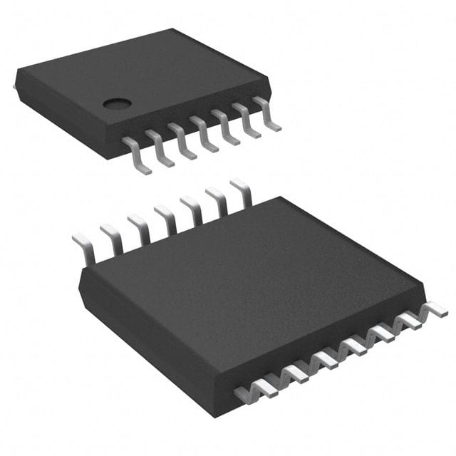
CD74HC14PW
Product Overview
- Category: Integrated Circuit (IC)
- Use: Inverter
- Characteristics: High-speed, CMOS technology
- Package: TSSOP (Thin Shrink Small Outline Package)
- Essence: Hex Schmitt Trigger Inverter
- Packaging/Quantity: Tape and Reel, 2500 units per reel
Specifications
- Supply Voltage Range: 2V to 6V
- Input Voltage Range: 0V to VCC
- Output Voltage Range: 0V to VCC
- Maximum Operating Frequency: 50 MHz
- Propagation Delay Time: 9 ns (typical)
- Quiescent Current: 2 µA (maximum)
Detailed Pin Configuration
The CD74HC14PW has a total of 14 pins. The pin configuration is as follows:
- Pin 1: Input A (Schmitt trigger input)
- Pin 2: Output A (inverted output of input A)
- Pin 3: Input B (Schmitt trigger input)
- Pin 4: Output B (inverted output of input B)
- Pin 5: Input C (Schmitt trigger input)
- Pin 6: Output C (inverted output of input C)
- Pin 7: Ground (GND)
- Pin 8: Power Supply (VCC)
- Pin 9: Input D (Schmitt trigger input)
- Pin 10: Output D (inverted output of input D)
- Pin 11: Input E (Schmitt trigger input)
- Pin 12: Output E (inverted output of input E)
- Pin 13: Input F (Schmitt trigger input)
- Pin 14: Output F (inverted output of input F)
Functional Features
- Hex Schmitt Trigger Inverter: The CD74HC14PW consists of six independent Schmitt trigger inverters. Each inverter has a hysteresis to provide noise immunity and improve signal integrity.
- High-Speed Operation: With CMOS technology, the CD74HC14PW offers high-speed operation, making it suitable for applications requiring fast switching times.
- Wide Voltage Range: The IC can operate within a supply voltage range of 2V to 6V, allowing flexibility in various electronic systems.
Advantages and Disadvantages
Advantages: - Noise Immunity: The Schmitt trigger inputs provide excellent noise immunity, ensuring reliable operation even in noisy environments. - Compact Package: The TSSOP package offers a small footprint, making it suitable for space-constrained applications. - Low Power Consumption: The CD74HC14PW has low quiescent current, resulting in reduced power consumption.
Disadvantages: - Limited Operating Frequency: The maximum operating frequency of 50 MHz may not be sufficient for certain high-speed applications. - Limited Voltage Range: The IC operates within a limited supply voltage range of 2V to 6V, which may not be compatible with all systems.
Working Principles
The CD74HC14PW is based on the Schmitt trigger concept. A Schmitt trigger is a circuit that converts an input signal into a digital output signal with hysteresis. It provides two threshold voltage levels, one for rising edge detection and another for falling edge detection. This hysteresis ensures stable output transitions and reduces the effects of noise.
In the CD74HC14PW, each Schmitt trigger inverter takes an input signal and produces an inverted output signal. The inputs are connected to the Schmitt trigger circuits, which compare the input voltage with predefined thresholds. When the input voltage crosses the rising threshold, the output switches to a logical low state. Conversely, when the input voltage crosses the falling threshold, the output switches to a logical high state.
Detailed Application Field Plans
The CD74HC14PW is widely used in various electronic applications, including:
- Signal Conditioning: The Schmitt trigger functionality makes it suitable for signal conditioning applications where noise immunity and clean signal transitions are crucial.
- Oscillators: The IC can be used to build oscillators for generating square wave signals with precise frequency and duty cycle control.
- Level Shifting: It can be employed as a level shifter to convert logic levels between different voltage domains.
- Pulse Shaping: The hysteresis provided by the Schmitt trigger helps in pulse shaping applications, ensuring well-defined output pulses.
Detailed and Complete Alternative Models
- SN74HC14N: This is a similar hex Schmitt trigger inverter IC from Texas Instruments, available in DIP (Dual Inline Package) format.
- MC74HC14AN: Another alternative from ON Semiconductor, offering the same functionality in a PDIP (Plastic Dual Inline Package) package.
- 74HCT14: This is a compatible IC from
Lista 10 Vanliga frågor och svar relaterade till tillämpningen av CD74HC14PW i tekniska lösningar
Sure! Here are 10 common questions and answers related to the application of CD74HC14PW in technical solutions:
Q: What is CD74HC14PW? A: CD74HC14PW is a hex inverter with Schmitt-trigger inputs, which means it can convert low-level signals to high-level signals and vice versa.
Q: What are the typical applications of CD74HC14PW? A: CD74HC14PW is commonly used in digital logic circuits, signal conditioning, waveform shaping, and noise filtering applications.
Q: What is the operating voltage range for CD74HC14PW? A: CD74HC14PW operates within a voltage range of 2V to 6V.
Q: How many inverters are there in CD74HC14PW? A: CD74HC14PW consists of six independent inverters.
Q: What is the maximum output current that CD74HC14PW can handle? A: CD74HC14PW can handle a maximum output current of 5.2mA.
Q: Can CD74HC14PW be used in high-speed applications? A: Yes, CD74HC14PW has a propagation delay of around 9ns, making it suitable for high-speed applications.
Q: Is CD74HC14PW compatible with both CMOS and TTL logic levels? A: Yes, CD74HC14PW is compatible with both CMOS and TTL logic levels.
Q: Can CD74HC14PW tolerate overvoltage conditions? A: No, CD74HC14PW is not designed to tolerate overvoltage conditions. It is recommended to stay within the specified voltage range.
Q: Does CD74HC14PW have built-in protection against electrostatic discharge (ESD)? A: Yes, CD74HC14PW has built-in ESD protection, which helps safeguard the device from damage during handling and assembly.
Q: Can CD74HC14PW be used in automotive applications? A: Yes, CD74HC14PW is suitable for automotive applications as it meets the necessary standards for automotive electronics.
Please note that these answers are general and may vary depending on specific datasheet specifications and application requirements.


