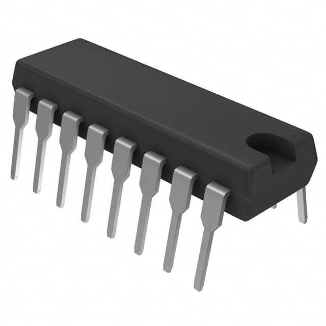
CD74ACT157E
Overview
- Category: Integrated Circuit (IC)
- Use: Data Selector/Multiplexer
- Characteristics: High-speed, low-power, 2-input multiplexer
- Package: 16-pin DIP (Dual In-line Package)
- Essence: CD74ACT157E is a versatile IC used for data selection and multiplexing purposes. It offers high-speed operation while consuming low power.
- Packaging/Quantity: Available in tubes or reels, with varying quantities depending on the supplier.
Specifications
- Logic Family: ACT
- Number of Inputs: 2
- Number of Outputs: 1
- Supply Voltage: 4.5V to 5.5V
- Operating Temperature Range: -40°C to +85°C
- Propagation Delay: 6ns (typical)
- Output Current: ±24mA
- Input Capacitance: 3pF (typical)
Pin Configuration
The CD74ACT157E has a 16-pin DIP package with the following pin configuration:
+---+--+---+
   A1 |1     16| VCC
   B1 |2     15| Y
   A0 |3     14| B
   B0 |4     13| C
   G1 |5     12| GND
   G2 |6     11| D
   G3 |7     10| E
   Y1 |8      9| F
       +--------+
Functional Features
- The CD74ACT157E is a 2-input multiplexer that selects one of the two input signals based on the control inputs.
- It operates at high speed, making it suitable for applications requiring fast data selection.
- The IC has a low power consumption, making it energy-efficient.
- It provides a single output that represents the selected input.
Advantages and Disadvantages
Advantages
- High-speed operation allows for quick data selection.
- Low power consumption results in energy efficiency.
- Versatile IC suitable for various applications.
- Compact 16-pin DIP package makes it easy to integrate into circuit designs.
Disadvantages
- Limited number of inputs and outputs.
- Requires external control signals for proper functioning.
Working Principles
The CD74ACT157E works based on the principle of multiplexing. It has two data inputs (A and B) and one output (Y). The control inputs (C and D) determine which input is selected and routed to the output. When C and D are set to specific logic levels, the corresponding input is transmitted to the output.
Detailed Application Field Plans
The CD74ACT157E can be used in various applications, including:
- Data routing in digital systems
- Address decoding in memory systems
- Signal selection in communication systems
- Input selection in microcontroller-based systems
- Multiplexing in data acquisition systems
Alternative Models
There are several alternative models available that serve similar functions to the CD74ACT157E. Some popular alternatives include:
- SN74LS157
- MC74HC157
- CD4052
- 74HC151
These alternative models offer similar features and can be used as replacements depending on specific requirements.
In conclusion, the CD74ACT157E is a versatile IC used for data selection and multiplexing purposes. Its high-speed operation, low power consumption, and compact package make it suitable for various applications. However, it has a limited number of inputs and outputs and requires external control signals for proper functioning. There are alternative models available that serve similar functions.
Lista 10 Vanliga frågor och svar relaterade till tillämpningen av CD74ACT157E i tekniska lösningar
Sure! Here are 10 common questions and answers related to the application of CD74ACT157E in technical solutions:
Q: What is CD74ACT157E? A: CD74ACT157E is a quad 2-input multiplexer IC (Integrated Circuit) that can be used for data selection and routing in digital circuits.
Q: What is the operating voltage range of CD74ACT157E? A: CD74ACT157E operates within a voltage range of 4.5V to 5.5V.
Q: How many inputs does CD74ACT157E have? A: CD74ACT157E has four data inputs, labeled A, B, C, and D.
Q: Can CD74ACT157E handle both analog and digital signals? A: No, CD74ACT157E is designed specifically for digital signals and is not suitable for handling analog signals.
Q: What is the output configuration of CD74ACT157E? A: CD74ACT157E has two outputs, labeled Y and Y̅ (Y-bar), which provide complementary outputs based on the selected input.
Q: What is the purpose of the enable pin (G) in CD74ACT157E? A: The enable pin (G) allows the user to control the operation of the multiplexer. When G is low (0), the outputs are disabled.
Q: Can CD74ACT157E be cascaded to increase the number of inputs? A: Yes, multiple CD74ACT157E ICs can be cascaded together to increase the number of inputs and achieve more complex data routing.
Q: What is the maximum frequency at which CD74ACT157E can operate? A: CD74ACT157E can operate at a maximum frequency of 125 MHz.
Q: Is CD74ACT157E compatible with TTL (Transistor-Transistor Logic) inputs? A: Yes, CD74ACT157E is designed to be compatible with TTL inputs, making it suitable for interfacing with TTL logic circuits.
Q: What are some common applications of CD74ACT157E? A: CD74ACT157E is commonly used in digital multiplexing, data routing, signal selection, and control applications in various electronic systems.
Please note that these answers are general and may vary depending on the specific requirements and implementation of CD74ACT157E in different technical solutions.


