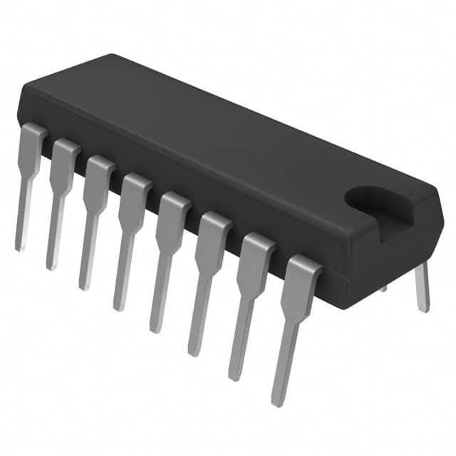
CD74ACT109E
Product Overview
- Category: Integrated Circuit
- Use: Digital Logic
- Characteristics: Dual J-K Positive Edge-Triggered Flip-Flop
- Package: 16-pin DIP (Dual In-line Package)
- Essence: This integrated circuit is a dual J-K positive edge-triggered flip-flop, which can be used in various digital logic applications.
- Packaging/Quantity: Available in reels or tubes, with a quantity of 250 units per reel/tube.
Specifications
- Supply Voltage: 4.5V to 5.5V
- Logic Family: ACT (Advanced CMOS Technology)
- Number of Flip-Flops: 2
- Trigger Type: Positive Edge-Triggered
- Clock Enable: Yes
- Propagation Delay: 8ns (typical)
- Operating Temperature Range: -40°C to +85°C
Detailed Pin Configuration
The CD74ACT109E has a total of 16 pins, each serving a specific purpose:
- Pin 1: Clock Input (CP1)
- Pin 2: Clock Enable Input (CE1)
- Pin 3: J-K Data Input (J1, K1)
- Pin 4: Q Output (Q1)
- Pin 5: Q Complement Output (Q̅1)
- Pin 6: Ground (GND)
- Pin 7: Q Complement Output (Q̅2)
- Pin 8: Q Output (Q2)
- Pin 9: J-K Data Input (J2, K2)
- Pin 10: Clock Enable Input (CE2)
- Pin 11: Clock Input (CP2)
- Pin 12: Set and Reset Inputs (S, R)
- Pin 13: Set and Reset Inputs (S̅, R̅)
- Pin 14: VCC (+5V Power Supply)
- Pin 15: Clock Output (CO)
- Pin 16: Clock Output (C̅O)
Functional Features
- Dual J-K positive edge-triggered flip-flop with set and reset inputs.
- Can be used as a synchronous counter, shift register, or for general-purpose storage applications.
- Positive edge-triggering allows synchronized data transfer.
- Clock enable inputs provide flexibility in controlling the clock signal.
- Set and reset inputs allow for initialization of the flip-flop's state.
Advantages and Disadvantages
Advantages
- Versatile functionality for various digital logic applications.
- High-speed operation due to ACT technology.
- Compact package size for space-constrained designs.
- Easy integration into existing circuitry.
Disadvantages
- Requires external components for complete functionality.
- Limited number of flip-flops per IC.
- Not suitable for low-voltage applications.
Working Principles
The CD74ACT109E operates based on the positive edge-triggered flip-flop principle. When the clock input (CP1 or CP2) receives a rising edge, the J-K data inputs (J1, K1, J2, K2) are sampled and transferred to the respective Q outputs (Q1, Q2). The clock enable inputs (CE1, CE2) control whether the clock signal is allowed to affect the flip-flop. The set and reset inputs (S, R, S̅, R̅) can be used to force the flip-flop into specific states.
Detailed Application Field Plans
The CD74ACT109E can be utilized in various digital logic applications, including but not limited to:
- Synchronous Counters: The flip-flop's positive edge-triggering and clock enable inputs make it suitable for building synchronous counters, which are widely used in digital systems for counting and sequencing purposes.
- Shift Registers: By connecting multiple CD74ACT109E flip-flops together, shift registers can be constructed. These are commonly employed for serial data storage and transfer applications.
- General-Purpose Storage: The flip-flop's ability to store binary information makes it useful for general-purpose storage applications, such as register files or memory elements.
Detailed and Complete Alternative Models
- SN74ACT109: Similar to the CD74ACT109E, this model is manufactured by Texas Instruments and offers the same functionality with minor variations in pin configuration.
- MC74ACT109: Produced by ON Semiconductor, this alternative model is functionally equivalent to the CD74ACT109E and can be used interchangeably.
In conclusion, the CD74ACT109E is a versatile dual J-K positive edge-triggered flip-flop integrated circuit. With its compact package, high-speed operation, and various application possibilities, it serves as a valuable component in digital logic designs.
Lista 10 Vanliga frågor och svar relaterade till tillämpningen av CD74ACT109E i tekniska lösningar
Sure! Here are 10 common questions and answers related to the application of CD74ACT109E in technical solutions:
Q: What is CD74ACT109E? A: CD74ACT109E is a dual JK flip-flop integrated circuit (IC) that can be used in various digital logic applications.
Q: What is the operating voltage range for CD74ACT109E? A: CD74ACT109E operates within a voltage range of 4.5V to 5.5V.
Q: What is the maximum clock frequency supported by CD74ACT109E? A: CD74ACT109E can support clock frequencies up to 100 MHz.
Q: How many flip-flops are there in CD74ACT109E? A: CD74ACT109E consists of two independent JK flip-flops.
Q: What is the purpose of the preset and clear inputs in CD74ACT109E? A: The preset and clear inputs allow you to set or reset the flip-flop outputs to specific states.
Q: Can CD74ACT109E be used in synchronous or asynchronous mode? A: CD74ACT109E can be used in both synchronous and asynchronous modes, depending on the application requirements.
Q: What is the typical propagation delay of CD74ACT109E? A: The typical propagation delay of CD74ACT109E is around 8 ns.
Q: Can CD74ACT109E drive external loads directly? A: CD74ACT109E has a high output drive capability, allowing it to drive standard TTL loads directly.
Q: Is CD74ACT109E compatible with other logic families? A: CD74ACT109E is compatible with a wide range of logic families, including TTL, CMOS, and LSTTL.
Q: What are some common applications of CD74ACT109E? A: CD74ACT109E can be used in applications such as counters, frequency dividers, shift registers, and general-purpose digital logic circuits.
Please note that these answers are general and may vary depending on specific datasheet specifications and application requirements.


