

CD4034BPW
Product Overview
Category
CD4034BPW belongs to the category of integrated circuits (ICs).
Use
This IC is commonly used in digital electronics for various applications such as counters, registers, and shift registers.
Characteristics
- CD4034BPW is a 12-stage parallel input/serial output static shift register.
- It operates on a wide voltage range, typically between 3V and 18V.
- The IC has a high noise immunity and can withstand harsh environmental conditions.
- It offers low power consumption, making it suitable for battery-powered devices.
- CD4034BPW has a compact package, allowing for easy integration into electronic circuits.
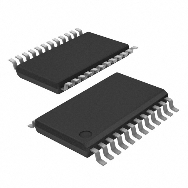
Package
The CD4034BPW is available in a 16-pin TSSOP (Thin Shrink Small Outline Package) format.
Essence
The essence of CD4034BPW lies in its ability to store and shift data in digital systems, enabling efficient data processing and control.
Packaging/Quantity
The IC is typically packaged in reels or tubes, with each reel containing 2500 units.
Specifications
- Supply Voltage: 3V - 18V
- Operating Temperature Range: -40°C to +85°C
- Input Voltage High Level (VIH): 2V - VDD
- Input Voltage Low Level (VIL): GND - 0.8V
- Output Voltage High Level (VOH): VDD - 0.5V
- Output Voltage Low Level (VOL): 0.5V
Detailed Pin Configuration
- Serial Data Input (DS)
- Clock Input (CP)
- Enable Input (EN)
- Parallel Data Inputs (D0-D11)
- Serial Data Output (Q12)
- Parallel Data Outputs (Q0-Q11)
- Ground (GND)
- Supply Voltage (VDD)
Functional Features
- CD4034BPW can be cascaded to form larger shift registers, allowing for expanded data storage capacity.
- It supports both parallel and serial data transfer modes, providing flexibility in different applications.
- The IC features an enable input that allows for easy control of data transfer operations.
- It has a synchronous clock input for precise timing of data shifting.
Advantages and Disadvantages
Advantages
- Wide operating voltage range enables compatibility with various systems.
- High noise immunity ensures reliable performance in noisy environments.
- Low power consumption makes it suitable for battery-powered devices.
- Compact package facilitates integration into electronic circuits.
Disadvantages
- Limited number of stages (12) may not suffice for certain complex applications.
- Lack of built-in error detection or correction mechanisms.
Working Principles
CD4034BPW operates based on the principle of sequential logic. It stores data in its internal memory and shifts it through the stages upon receiving clock pulses. The parallel data inputs allow for loading data into the register, while the serial data output provides the shifted data. The enable input controls the data transfer operation.
Detailed Application Field Plans
CD4034BPW finds applications in various digital systems, including but not limited to: 1. Industrial automation: Used in control systems for monitoring and controlling processes. 2. Communication equipment: Employed in data transmission and reception circuits. 3. Consumer electronics: Integrated into devices like digital clocks, calculators, and remote controls. 4. Automotive electronics: Utilized in vehicle control units and dashboard displays. 5. Medical devices: Incorporated into medical equipment for data processing and control.
Detailed and Complete Alternative Models
- CD4021B: 8-stage parallel input/serial output shift register.
- CD4094B: 8-stage serial input/parallel output shift register.
- CD4015B: Dual 4-stage static shift register.
These alternative models offer similar functionality to CD4034BPW and can be considered as substitutes in different applications.
Word count: 518 words
Lista 10 Vanliga frågor och svar relaterade till tillämpningen av CD4034BPW i tekniska lösningar
Sure! Here are 10 common questions and answers related to the application of CD4034BPW in technical solutions:
Q: What is CD4034BPW? A: CD4034BPW is a 8-stage serial-in/parallel-out shift register IC (integrated circuit) commonly used in digital electronics.
Q: What is the purpose of CD4034BPW? A: CD4034BPW is used for data storage, conversion, and transfer in various applications such as counters, LED displays, and control systems.
Q: How does CD4034BPW work? A: CD4034BPW receives serial data input and shifts it through its internal registers. The parallel outputs can then be accessed to retrieve the stored data.
Q: What is the maximum clock frequency supported by CD4034BPW? A: CD4034BPW can operate at a maximum clock frequency of 5 MHz.
Q: How many parallel outputs does CD4034BPW have? A: CD4034BPW has 8 parallel outputs, each representing a stage of the shift register.
Q: Can CD4034BPW be cascaded to increase the number of stages? A: Yes, multiple CD4034BPW ICs can be cascaded together to increase the number of stages and expand the storage capacity.
Q: What is the power supply voltage range for CD4034BPW? A: CD4034BPW operates within a power supply voltage range of 3V to 18V.
Q: Does CD4034BPW support both CMOS and TTL logic levels? A: Yes, CD4034BPW is compatible with both CMOS and TTL logic levels, making it versatile for different applications.
Q: Can CD4034BPW be used in battery-powered devices? A: Yes, CD4034BPW has a low power consumption and can be used in battery-powered devices.
Q: Are there any specific precautions to consider when using CD4034BPW? A: It is important to ensure proper decoupling capacitors are used near the power supply pins of CD4034BPW to minimize noise and voltage fluctuations. Additionally, care should be taken to avoid exceeding the maximum ratings specified in the datasheet.
Please note that these answers are general and may vary depending on the specific application and requirements. Always refer to the datasheet and consult with technical documentation for accurate information.