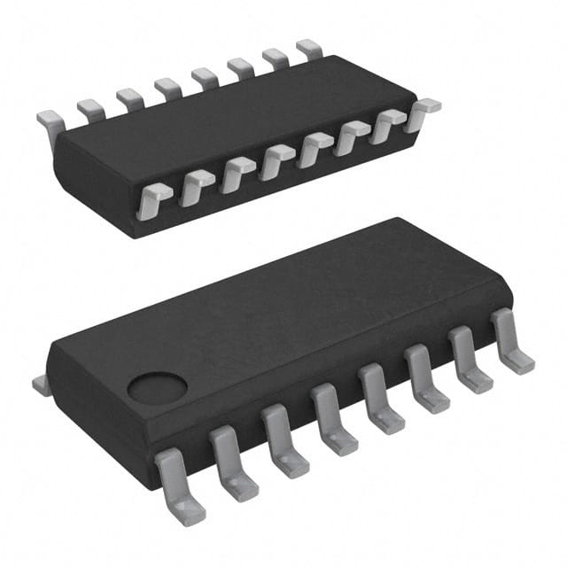
CD4027BM96E4
Product Overview
- Category: Integrated Circuit (IC)
- Use: Flip-Flop
- Characteristics: Dual J-K Master-Slave Flip-Flop, CMOS Technology
- Package: SOIC-16
- Essence: Sequential Logic
- Packaging/Quantity: Tape and Reel, 2500 units per reel
Specifications
- Supply Voltage Range: 3V to 18V
- Logic Family: CMOS
- Number of Flip-Flops: 2
- Clock Trigger Type: Positive Edge
- Propagation Delay Time: 60 ns (typical)
- Operating Temperature Range: -55°C to +125°C
Detailed Pin Configuration
The CD4027BM96E4 has a total of 16 pins. The pin configuration is as follows:
- J1 - J input for Flip-Flop 1
- K1 - K input for Flip-Flop 1
- Q1 - Output of Flip-Flop 1
- CP1 - Clock input for Flip-Flop 1
- VSS - Ground
- Q1 - Complementary output of Flip-Flop 1
- Q2 - Output of Flip-Flop 2
- CP2 - Clock input for Flip-Flop 2
- K2 - K input for Flip-Flop 2
- J2 - J input for Flip-Flop 2
- VDD - Supply voltage
- NC - No connection
- NC - No connection
- NC - No connection
- NC - No connection
- VSS - Ground
Functional Features
- Dual J-K Master-Slave Flip-Flop with individual clock inputs
- Positive-edge triggered clock inputs
- Direct overriding clear (CLR) input for each Flip-Flop
- Buffered Q and Q̅ outputs
Advantages and Disadvantages
Advantages: - Dual Flip-Flop in a single package, saving board space - CMOS technology offers low power consumption - Wide supply voltage range allows flexibility in various applications - Positive-edge triggering ensures reliable operation
Disadvantages: - Propagation delay time may limit the maximum operating frequency - Limited number of Flip-Flops per package
Working Principles
The CD4027BM96E4 is a dual J-K Master-Slave Flip-Flop implemented using CMOS technology. Each Flip-Flop has its own clock input, J and K inputs, and complementary outputs. The positive-edge triggered clock inputs allow synchronous operation.
The J-K inputs determine the state of the Flip-Flop based on the current state and the clock signal. The outputs change according to the input conditions and clock transitions. The direct overriding clear (CLR) input can asynchronously reset the Flip-Flops to a known state.
Detailed Application Field Plans
The CD4027BM96E4 is commonly used in various digital systems where sequential logic is required. Some application fields include:
- Counters and frequency dividers
- Shift registers
- Data storage and retrieval systems
- Control circuits
- Timing and synchronization circuits
Detailed and Complete Alternative Models
- CD4027BE - DIP-16 package, same functionality as CD4027BM96E4
- MC14027B - SOIC-14 package, similar functionality with fewer pins
- HEF4027BP - DIP-16 package, compatible with CD4027BM96E4
These alternative models offer similar or equivalent functionality to the CD4027BM96E4 and can be used as replacements in various applications.
Word count: 431 words
Lista 10 Vanliga frågor och svar relaterade till tillämpningen av CD4027BM96E4 i tekniska lösningar
What is the function of CD4027BM96E4 in technical solutions?
- The CD4027BM96E4 is a dual J-K flip-flop IC used for various applications such as frequency division, time delay generation, and data storage.How many flip-flops are there in CD4027BM96E4?
- The CD4027BM96E4 contains two independent J-K flip-flops within a single package.What is the maximum operating voltage for CD4027BM96E4?
- The maximum operating voltage for CD4027BM96E4 is typically 18V.Can CD4027BM96E4 be used for frequency division?
- Yes, CD4027BM96E4 can be used for frequency division by connecting the Q output of one flip-flop to the clock input of the other.What is the typical power consumption of CD4027BM96E4?
- The typical power consumption of CD4027BM96E4 is low, making it suitable for battery-powered applications.How does CD4027BM96E4 handle asynchronous inputs?
- CD4027BM96E4 features asynchronous preset and clear inputs to initialize the flip-flop states.Can CD4027BM96E4 be cascaded for larger count lengths?
- Yes, multiple CD4027BM96E4 ICs can be cascaded to achieve larger count lengths or more complex sequential logic functions.What are the recommended operating conditions for CD4027BM96E4?
- The recommended operating conditions include a specified range of supply voltage, temperature, and input signal levels.Is CD4027BM96E4 suitable for use in automotive electronics?
- Yes, CD4027BM96E4 is often used in automotive electronics due to its reliability and performance under varying environmental conditions.Are there any application notes or reference designs available for CD4027BM96E4?
- Yes, the manufacturer provides application notes and reference designs to assist with the implementation of CD4027BM96E4 in technical solutions.


