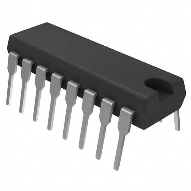
CD4018BE
Product Overview
- Category: Integrated Circuit (IC)
- Use: Counter/Divider
- Characteristics:
- 8-bit synchronous counter with parallel load
- Low power consumption
- Wide operating voltage range
- High noise immunity
- Package: DIP-16 (Dual In-line Package, 16 pins)
- Essence: The CD4018BE is a versatile counter/divider IC that can be used in various digital applications.
- Packaging/Quantity: Available in tubes or reels, with 25 pieces per tube/reel.
Specifications
- Supply Voltage Range: 3V to 18V
- Operating Temperature Range: -55°C to +125°C
- Maximum Clock Frequency: 5MHz
- Maximum Counting Range: 256 (2^8)
Pin Configuration
The CD4018BE has 16 pins arranged as follows:
┌───┬───┐
 1 │       │ 16
   │       │
 2 │       │ 15
   │       │
 3 │       │ 14
   │       │
 4 │       │ 13
   │       │
 5 │       │ 12
   │       │
 6 │       │ 11
   │       │
 7 │       │ 10
   │       │
 8 │       │ 9
   └───┴───┘
Functional Features
- Synchronous counting with parallel load capability
- Reset function to clear the counter
- Carry output for cascading multiple counters
- Enable input to control counting operation
- Schmitt trigger inputs for improved noise immunity
Advantages and Disadvantages
Advantages
- Versatile and widely used in digital applications
- Low power consumption makes it suitable for battery-powered devices
- Wide operating voltage range allows compatibility with various systems
- High noise immunity ensures reliable operation in noisy environments
Disadvantages
- Limited counting range (up to 256)
- Requires external components for more complex operations
- Not suitable for high-frequency applications
Working Principles
The CD4018BE is a synchronous counter that counts up or down based on the clock input. It can be loaded with a parallel value using the load input, and the count can be reset using the reset input. The carry output allows cascading multiple counters to achieve larger counting ranges.
Detailed Application Field Plans
The CD4018BE can be used in various digital applications, including:
- Frequency division: Dividing an input frequency by a specific factor.
- Event counting: Counting the occurrence of specific events.
- Time delay generation: Generating precise time delays.
- Address decoding: Decoding addresses in memory or peripheral systems.
- Sequence generation: Generating specific sequences of outputs.
Alternative Models
Here are some alternative models that can be used as replacements for the CD4018BE:
- CD4020BE: 14-bit binary counter/divider.
- CD4518BE: Dual BCD up-counter.
- CD74HC4018E: High-speed CMOS 8-stage presettable synchronous down counter.
These alternatives offer similar functionalities and can be used depending on specific requirements.
In conclusion, the CD4018BE is a versatile counter/divider IC with various applications in digital systems. Its low power consumption, wide operating voltage range, and high noise immunity make it a popular choice among designers. However, its limited counting range and need for external components should be considered when selecting this IC for a particular application.
Lista 10 Vanliga frågor och svar relaterade till tillämpningen av CD4018BE i tekniska lösningar
Sure! Here are 10 common questions and answers related to the application of CD4018BE in technical solutions:
Q: What is CD4018BE? A: CD4018BE is a CMOS 4-bit parallel-in/parallel-out shift register with asynchronous reset.
Q: What are the typical applications of CD4018BE? A: CD4018BE is commonly used in digital circuits for tasks such as data storage, serial-to-parallel conversion, and parallel-to-serial conversion.
Q: How many bits can CD4018BE store? A: CD4018BE can store up to 4 bits of data.
Q: Can CD4018BE be cascaded to increase the number of bits stored? A: Yes, multiple CD4018BE chips can be cascaded together to increase the number of bits stored.
Q: What is the maximum clock frequency supported by CD4018BE? A: CD4018BE can typically operate at clock frequencies up to several megahertz (MHz).
Q: Does CD4018BE require external power supply voltage regulation? A: Yes, CD4018BE requires an external power supply voltage between 3V and 18V, which should be regulated and stable.
Q: Can CD4018BE handle both positive and negative edge-triggered clocks? A: No, CD4018BE is only designed to work with positive edge-triggered clocks.
Q: What is the power consumption of CD4018BE? A: The power consumption of CD4018BE depends on various factors, but it is generally low due to its CMOS technology.
Q: Are there any specific precautions to consider when using CD4018BE? A: It is important to ensure proper decoupling and bypass capacitors are used near the power supply pins of CD4018BE to minimize noise and voltage fluctuations.
Q: Can CD4018BE be used in both digital and analog circuits? A: No, CD4018BE is specifically designed for digital circuit applications and is not suitable for use in analog circuits.
I hope these questions and answers help! Let me know if you have any more queries.


