

STGF7H60DF
Introduction
The STGF7H60DF is a power semiconductor device belonging to the category of Insulated Gate Bipolar Transistors (IGBTs). This entry provides an overview of the basic information, specifications, pin configuration, functional features, advantages and disadvantages, working principles, application field plans, and alternative models of the STGF7H60DF.
Basic Information Overview
- Category: Insulated Gate Bipolar Transistor (IGBT)
- Use: Power switching applications in various electronic devices and systems
- Characteristics: High voltage capability, low saturation voltage, fast switching speed
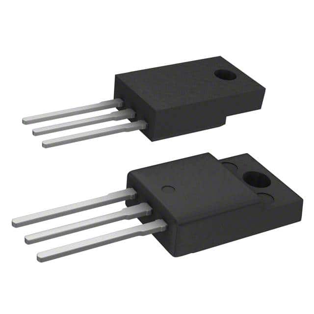
- Package: TO-220FP
- Essence: Power control and conversion
- Packaging/Quantity: Typically packaged individually
Specifications
- Voltage Rating: 600V
- Current Rating: 75A
- Maximum Power Dissipation: 150W
- Operating Temperature Range: -55°C to 150°C
- Gate-Emitter Voltage: ±20V
Detailed Pin Configuration
The STGF7H60DF IGBT typically features the following pin configuration: 1. Collector (C) 2. Gate (G) 3. Emitter (E)
Functional Features
- High voltage capability for power applications
- Low saturation voltage for efficient power switching
- Fast switching speed for improved performance
- Built-in freewheeling diode for inductive load protection
Advantages and Disadvantages
Advantages
- High voltage capability enables use in diverse power applications
- Low saturation voltage reduces power losses during operation
- Fast switching speed enhances overall system efficiency
Disadvantages
- Higher cost compared to traditional power transistors
- Sensitivity to overvoltage conditions requires additional protective circuitry
Working Principles
The STGF7H60DF operates based on the principles of controlling the flow of current between the collector and emitter terminals using the gate signal. When a suitable voltage is applied to the gate terminal, it allows the current to flow through the device, enabling power control and conversion in electronic circuits.
Detailed Application Field Plans
The STGF7H60DF finds extensive application in various fields, including: - Industrial motor drives - Uninterruptible power supplies (UPS) - Renewable energy systems - Electric vehicle powertrains - Power inverters for consumer electronics
Detailed and Complete Alternative Models
Some alternative models to the STGF7H60DF include: - STGW30NC60WD - IRG4BC20UD - FGA25N120ANTD
In conclusion, the STGF7H60DF IGBT offers high voltage capability, low saturation voltage, and fast switching speed, making it suitable for diverse power switching applications across different industries.
Word count: 345
Lista 10 Vanliga frågor och svar relaterade till tillämpningen av STGF7H60DF i tekniska lösningar
What is STGF7H60DF?
- STGF7H60DF is a high voltage, fast-switching N-channel IGBT (Insulated Gate Bipolar Transistor) designed for use in various power electronic applications.
What are the key features of STGF7H60DF?
- The key features of STGF7H60DF include a high voltage capability, low on-state voltage drop, fast switching speed, and integrated freewheeling diode.
In what technical solutions can STGF7H60DF be used?
- STGF7H60DF can be used in applications such as motor drives, induction heating, welding equipment, and power supplies.
What is the maximum voltage and current rating of STGF7H60DF?
- The maximum voltage rating of STGF7H60DF is typically around 600V, and the maximum current rating is around 30A.
How does STGF7H60DF compare to other IGBTs in terms of performance?
- STGF7H60DF offers a good balance of high voltage capability, low on-state voltage drop, and fast switching speed compared to other IGBTs in its class.
What are the thermal considerations when using STGF7H60DF?
- Proper heat sinking and thermal management are important when using STGF7H60DF to ensure optimal performance and reliability.
Can STGF7H60DF be used in parallel configurations for higher current applications?
- Yes, STGF7H60DF can be used in parallel configurations to increase the current handling capability for higher power applications.
Are there any specific driver requirements for driving STGF7H60DF?
- It is recommended to use dedicated gate driver ICs designed for driving IGBTs to ensure proper switching and protection of STGF7H60DF.
What are the typical switching frequencies achievable with STGF7H60DF?
- STGF7H60DF can achieve typical switching frequencies ranging from a few kHz to several tens of kHz, depending on the application requirements.
What are the common protection features available in STGF7H60DF?
- STGF7H60DF typically includes built-in overcurrent protection, short-circuit protection, and temperature sensing to enhance system reliability and safety.