

TIP131 Transistor: Encyclopedia Entry
Introduction
The TIP131 is a power Darlington transistor that belongs to the category of electronic components. It is widely used in various electronic circuits due to its high current and voltage capabilities. This entry provides an overview of the TIP131, including its basic information, specifications, pin configuration, functional features, advantages and disadvantages, working principles, application field plans, and alternative models.
Basic Information Overview
- Category: Electronic Component
- Use: Power Amplification and Switching
- Characteristics: High Current and Voltage Capabilities
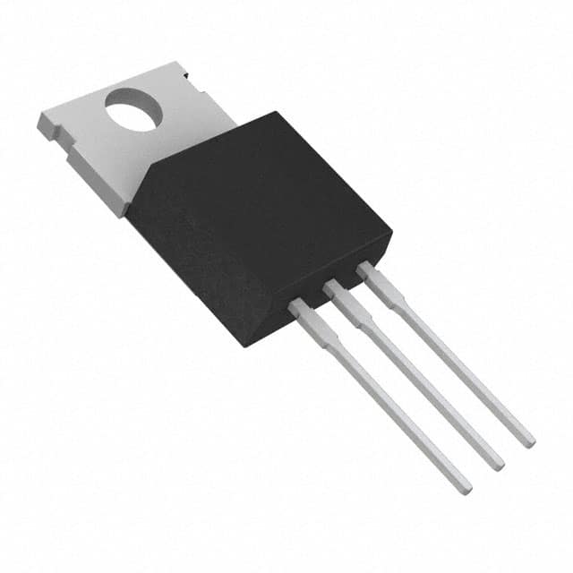
- Package: TO-220
- Essence: Power Darlington Transistor
- Packaging/Quantity: Typically Sold Individually
Specifications
- Collector-Emitter Voltage (VCEO): 100V
- Collector-Base Voltage (VCBO): 100V
- Emitter-Base Voltage (VEBO): 5V
- Collector Current (IC): 8A
- Power Dissipation (PD): 2W
- Transition Frequency (FT): 3MHz
Detailed Pin Configuration
The TIP131 transistor has a standard TO-220 package with three pins: 1. Base (B): Input terminal for controlling the flow of current. 2. Collector (C): Output terminal where the current exits. 3. Emitter (E): Terminal through which the current enters.
Functional Features
- High Gain: The Darlington pair configuration provides high current gain.
- Robustness: Capable of handling high currents and voltages.
- Low Saturation Voltage: Ensures minimal power loss during switching.
Advantages and Disadvantages
Advantages
- High Current Gain
- Low Saturation Voltage
- Robust Construction
Disadvantages
- Slower Switching Speed Compared to Some Alternative Models
- Relatively Higher Cost
Working Principles
The TIP131 operates based on the principles of amplification and switching. When a small current is applied to the base terminal, it controls a much larger current flowing between the collector and emitter terminals, allowing for power amplification and switching functions.
Detailed Application Field Plans
The TIP131 is commonly used in the following applications: - Power Amplifiers - Motor Control Circuits - LED Drivers - Solenoid Drivers - Relay Drivers
Detailed and Complete Alternative Models
Some alternative models to the TIP131 include: - TIP132 - TIP137 - TIP142 - TIP147
In summary, the TIP131 transistor is a versatile electronic component with high current and voltage capabilities, making it suitable for various power amplification and switching applications. Its robustness and high gain make it a popular choice in electronic circuit design.
[Word Count: 366]
Lista 10 Vanliga frågor och svar relaterade till tillämpningen av TIP131 i tekniska lösningar
What is TIP131?
- TIP131 is a PNP Darlington transistor commonly used for high-power switching applications.
What are the typical applications of TIP131?
- TIP131 is often used in applications such as relay drivers, lamp drivers, motor controls, and other high-current switching circuits.
What is the maximum collector current rating of TIP131?
- The maximum collector current rating of TIP131 is 8 amperes.
What is the maximum collector-emitter voltage rating of TIP131?
- The maximum collector-emitter voltage rating of TIP131 is 100 volts.
How do I connect TIP131 in a relay driver circuit?
- To use TIP131 in a relay driver circuit, you would typically connect the relay coil between the collector and the positive supply voltage, with the emitter connected to ground through a current-limiting resistor.
Can TIP131 be used for PWM (Pulse Width Modulation) applications?
- Yes, TIP131 can be used in PWM applications to control the speed of motors or dim the brightness of lamps.
What is the thermal resistance of TIP131?
- The thermal resistance of TIP131 is approximately 2.5°C/W.
How do I ensure proper heat dissipation when using TIP131 in high-power applications?
- It's important to use a suitable heat sink with TIP131 to ensure proper heat dissipation and prevent overheating.
Can TIP131 be used in automotive applications?
- Yes, TIP131 can be used in automotive applications such as controlling motors or driving high-power loads.
What are some common alternatives to TIP131 for high-power switching applications?
- Some common alternatives to TIP131 include TIP132, TIP142, and TIP147, which offer similar characteristics and performance for high-power switching solutions.