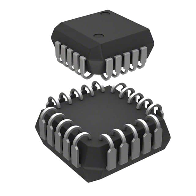
MC10H117FNR2G
Product Overview
Category
MC10H117FNR2G belongs to the category of integrated circuits (ICs).
Use
This product is commonly used in electronic devices for signal processing and amplification.
Characteristics
- High-speed operation
- Low power consumption
- Wide operating voltage range
- Small package size
Package
MC10H117FNR2G is available in a small outline integrated circuit (SOIC) package.
Essence
The essence of MC10H117FNR2G lies in its ability to process and amplify signals efficiently and accurately.
Packaging/Quantity
This product is typically packaged in reels or tubes, with a quantity of 250 units per reel/tube.
Specifications
- Supply Voltage: 3.0V to 5.5V
- Operating Temperature Range: -40°C to +85°C
- Input Voltage Range: -1.5V to VCC + 1.5V
- Output Voltage Range: -1.5V to VCC + 1.5V
- Maximum Propagation Delay: 2.5ns
Detailed Pin Configuration
MC10H117FNR2G has a total of 16 pins arranged as follows:
- Pin 1: Input A
- Pin 2: Input B
- Pin 3: Input C
- Pin 4: Input D
- Pin 5: Output Y
- Pin 6: Output YB
- Pin 7: GND
- Pin 8: VCC
- Pin 9: Input E
- Pin 10: Input F
- Pin 11: Input G
- Pin 12: Input H
- Pin 13: Output YA
- Pin 14: Output YBA
- Pin 15: NC (No Connection)
- Pin 16: NC (No Connection)
Functional Features
- High-speed AND/OR gate functionality
- Differential inputs for improved noise immunity
- Complementary outputs for ease of use in various applications
- Wide operating voltage range allows compatibility with different systems
Advantages and Disadvantages
Advantages
- High-speed operation enables efficient signal processing
- Low power consumption helps conserve energy
- Wide operating voltage range ensures compatibility with various systems
- Small package size saves board space
Disadvantages
- Limited number of input/output pins may restrict complex circuit designs
- Propagation delay of 2.5ns may not be suitable for ultra-high-speed applications
Working Principles
MC10H117FNR2G operates based on the principles of logic gates, specifically AND/OR gates. It takes multiple input signals and performs logical operations to produce the desired output. The differential inputs provide improved noise immunity, ensuring accurate signal processing.
Detailed Application Field Plans
MC10H117FNR2G finds applications in various fields, including: 1. Telecommunications: Signal amplification and processing in communication systems. 2. Industrial Automation: Control and monitoring circuits in industrial automation equipment. 3. Automotive Electronics: Interface circuits for automotive control units. 4. Consumer Electronics: Signal processing in audio/video devices and gaming consoles. 5. Medical Devices: Circuitry for medical imaging and diagnostic equipment.
Detailed and Complete Alternative Models
Some alternative models that offer similar functionality to MC10H117FNR2G are: 1. MC100EP116FAR2G 2. MC100ELT21DR2G 3. MC100LVEL11DTR2G 4. MC100LVEP210MNR4G 5. MC100LVEP210MNG
These alternative models can be considered based on specific requirements and compatibility with the application.
Word count: 520 words
Lista 10 Vanliga frågor och svar relaterade till tillämpningen av MC10H117FNR2G i tekniska lösningar
Sure! Here are 10 common questions and answers related to the application of MC10H117FNR2G in technical solutions:
Question: What is MC10H117FNR2G?
Answer: MC10H117FNR2G is a high-speed ECL (Emitter-Coupled Logic) quad differential line receiver.Question: What is the operating voltage range for MC10H117FNR2G?
Answer: The operating voltage range for MC10H117FNR2G is typically between -4.2V and -5.7V.Question: What is the maximum data rate supported by MC10H117FNR2G?
Answer: MC10H117FNR2G supports a maximum data rate of 500 Mbps.Question: Can MC10H117FNR2G be used in low-power applications?
Answer: No, MC10H117FNR2G is not suitable for low-power applications as it operates at higher power levels.Question: What is the input common-mode voltage range for MC10H117FNR2G?
Answer: The input common-mode voltage range for MC10H117FNR2G is typically between -2.0V and -4.0V.Question: Does MC10H117FNR2G have built-in termination resistors?
Answer: No, MC10H117FNR2G does not have built-in termination resistors. External termination resistors are required for proper operation.Question: Can MC10H117FNR2G be used in high-speed communication systems?
Answer: Yes, MC10H117FNR2G is designed for high-speed applications such as telecommunications and data communication systems.Question: What is the output voltage swing of MC10H117FNR2G?
Answer: The output voltage swing of MC10H117FNR2G is typically between -1.8V and -3.0V.Question: Is MC10H117FNR2G compatible with other logic families?
Answer: MC10H117FNR2G is not directly compatible with other logic families, as it operates on ECL levels. Level translation may be required for interfacing with other logic families.Question: Can MC10H117FNR2G be used in automotive applications?
Answer: Yes, MC10H117FNR2G is suitable for automotive applications that require high-speed data transmission and robust performance.
Please note that these answers are general and may vary depending on specific application requirements and datasheet specifications.


