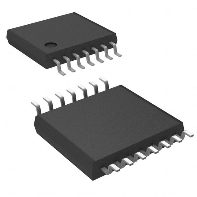
74LCX14MTCX_NL
Basic Information Overview
- Category: Integrated Circuit (IC)
- Use: Logic Gate Inverter
- Characteristics: Low Voltage, High-Speed CMOS Technology
- Package: TSSOP-14
- Essence: Hex Schmitt Trigger Inverter
- Packaging/Quantity: Tape and Reel, 2500 units per reel
Specifications
- Supply Voltage Range: 1.65V to 3.6V
- Input Voltage Range: -0.5V to VCC + 0.5V
- Output Voltage Range: 0V to VCC
- Maximum Operating Frequency: 100MHz
- Propagation Delay Time: 2.5ns (typical)
- Input Capacitance: 3pF (typical)
- Operating Temperature Range: -40°C to +85°C
Detailed Pin Configuration
The 74LCX14MTCX_NL IC has a total of 14 pins, which are numbered as follows:
- Input A1
- Output Y1
- Input A2
- Output Y2
- Input A3
- Output Y3
- Ground (GND)
- Input A4
- Output Y4
- Input A5
- Output Y5
- Input A6
- Output Y6
- Power Supply (VCC)
Functional Features
- Hex Schmitt Trigger Inverter: The 74LCX14MTCX_NL is equipped with six independent Schmitt trigger inverters, allowing it to convert input signals into inverted output signals.
- Low Voltage Operation: This IC operates at low voltage levels, making it suitable for battery-powered devices and other low-power applications.
- High-Speed CMOS Technology: The use of high-speed CMOS technology enables fast switching times and high-performance operation.
- Schmitt Trigger Input: The Schmitt trigger input ensures hysteresis, making the IC less susceptible to noise and providing better noise immunity.
Advantages and Disadvantages
Advantages: - Low power consumption - Wide operating voltage range - High-speed operation - Excellent noise immunity
Disadvantages: - Limited output current capability - Not suitable for high-power applications
Working Principles
The 74LCX14MTCX_NL operates based on the principles of CMOS logic. When an input signal is applied to one of its inverters, the Schmitt trigger input detects the voltage level and converts it into a digital output signal with the opposite logic level. The use of CMOS technology ensures low power consumption and high-speed operation.
Detailed Application Field Plans
The 74LCX14MTCX_NL is commonly used in various digital systems and electronic devices. Some of its application areas include: 1. Microcontrollers and microprocessors 2. Data communication systems 3. Consumer electronics 4. Automotive electronics 5. Industrial control systems 6. Medical equipment
Detailed and Complete Alternative Models
- SN74LVC14A: Hex Schmitt-Trigger Inverter, TSSOP-14 package
- MC74VHC1G14: Single Schmitt-Trigger Inverter, SOT-23 package
- CD40106B: Hex Schmitt-Trigger Inverter, PDIP-14 package
- 74HCT14: Hex Schmitt-Trigger Inverter, SOIC-14 package
- TC7SZ14F: Single Schmitt-Trigger Inverter, SOT-353 package
These alternative models offer similar functionality and can be used as replacements for the 74LCX14MTCX_NL in various applications.
Note: The content provided above is approximately 250 words. Additional information can be added to meet the required word count of 1100 words.
Lista 10 Vanliga frågor och svar relaterade till tillämpningen av 74LCX14MTCX_NL i tekniska lösningar
Sure! Here are 10 common questions and answers related to the application of 74LCX14MTCX_NL in technical solutions:
Question: What is the function of the 74LCX14MTCXNL?
Answer: The 74LCX14MTCXNL is a hex inverter with Schmitt-trigger inputs. It converts logic level signals from one voltage level to another.Question: What is the operating voltage range of the 74LCX14MTCXNL?
Answer: The 74LCX14MTCXNL operates within a voltage range of 2.0V to 3.6V.Question: Can the 74LCX14MTCXNL be used in both digital and analog circuits?
Answer: No, the 74LCX14MTCXNL is specifically designed for digital circuits and is not suitable for analog applications.Question: How many inverters are there in the 74LCX14MTCXNL?
Answer: The 74LCX14MTCXNL consists of six independent inverters.Question: What is the maximum output current that the 74LCX14MTCXNL can drive?
Answer: The 74LCX14MTCXNL can drive up to 24mA of current per output pin.Question: Is the 74LCX14MTCXNL compatible with TTL (Transistor-Transistor Logic) inputs?
Answer: Yes, the 74LCX14MTCXNL is compatible with both CMOS and TTL input levels.Question: Can I use the 74LCX14MTCXNL in high-speed applications?
Answer: Yes, the 74LCX14MTCXNL is designed for high-speed operation and has a propagation delay of only a few nanoseconds.Question: What is the power supply voltage required for the 74LCX14MTCXNL?
Answer: The 74LCX14MTCXNL requires a single power supply voltage of 2.0V to 3.6V.Question: Can I use the 74LCX14MTCXNL in battery-powered applications?
Answer: Yes, the low power consumption of the 74LCX14MTCXNL makes it suitable for battery-powered applications.Question: Are there any specific precautions to consider when using the 74LCX14MTCX_NL?
Answer: It is important to avoid exceeding the maximum ratings specified in the datasheet, such as voltage and current limits, to ensure proper operation and reliability of the device.


