

Encyclopedia Entry: 74F574PC
Product Overview
Category
The 74F574PC belongs to the category of integrated circuits (ICs), specifically a flip-flop IC.
Use
This IC is commonly used in digital electronics for storing and transferring binary data. It can be employed in various applications such as memory units, registers, and data storage systems.
Characteristics
- The 74F574PC is a high-speed, octal D-type flip-flop with a transparent latch.
- It operates on a wide voltage range, typically between 4.5V and 5.5V.
- This IC offers excellent noise immunity and low power consumption.
- It is designed to work in both commercial and industrial temperature ranges.
- The 74F574PC is compatible with TTL (Transistor-Transistor Logic) and CMOS (Complementary Metal-Oxide-Semiconductor) logic families.
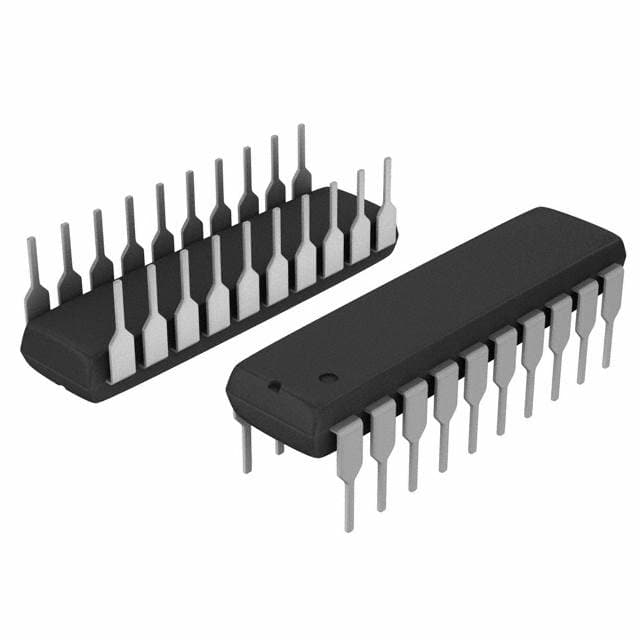
Package and Quantity
The 74F574PC is available in a 20-pin plastic dual-inline package (PDIP). It is commonly sold in reels or tubes containing multiple units, with quantities varying based on the supplier's packaging standards.
Specifications
- Supply Voltage Range: 4.5V to 5.5V
- Input Voltage Range: 0V to Vcc
- Output Voltage Range: 0V to Vcc
- Operating Temperature Range: -40°C to +85°C
- Maximum Clock Frequency: 100 MHz
- Propagation Delay Time: 6 ns (typical)
Pin Configuration
The 74F574PC has a total of 20 pins, each serving a specific function. Here is the detailed pin configuration:
- D0: Data input 0
- D1: Data input 1
- D2: Data input 2
- D3: Data input 3
- D4: Data input 4
- D5: Data input 5
- D6: Data input 6
- D7: Data input 7
- GND: Ground (0V)
- Q0: Output 0
- Q1: Output 1
- Q2: Output 2
- Q3: Output 3
- Q4: Output 4
- Q5: Output 5
- Q6: Output 6
- Q7: Output 7
- OE: Output Enable
- CP: Clock Pulse
- Vcc: Supply Voltage
Functional Features
The 74F574PC offers the following functional features:
- Transparent latch: The IC has a transparent latch that allows data to be transferred to the outputs when the clock pulse is active.
- Octal flip-flop: It consists of eight individual D-type flip-flops, allowing simultaneous storage and transfer of eight bits of data.
- Output enable control: The OE pin enables or disables the outputs, providing flexibility in controlling data flow.
- High-speed operation: With a maximum clock frequency of 100 MHz, this IC is suitable for applications requiring fast data processing.
Advantages and Disadvantages
Advantages
- High-speed operation makes it suitable for time-critical applications.
- Wide voltage range compatibility allows for versatile integration with different systems.
- Excellent noise immunity ensures reliable data storage and transfer.
- Low power consumption contributes to energy-efficient designs.
Disadvantages
- Limited output current capacity may restrict its use in certain high-current applications.
- Availability may vary depending on the supplier and market demand.
Working Principles
The 74F574PC operates based on the principles of flip-flops and latches. When the clock pulse is active, the data inputs are transferred to the outputs. The transparent latch allows real-time data storage and transfer, ensuring accurate and synchronized information flow.
Application Field Plans
The 74F574PC finds applications in various fields, including:
- Computer memory systems
- Data registers
- Microcontrollers
- Digital signal processing
- Communication systems
- Industrial automation
Its versatility and compatibility with different logic families make it suitable for a wide range of digital electronics applications.
Alternative Models
Several alternative models can be considered as substitutes for the 74F574PC, depending on specific requirements and availability. Some popular alternatives include:
- 74HC574: A CMOS-based octal D-type flip-flop with similar functionality.
- SN74LS374: A TTL-based octal D-type flip-flop with tri-state outputs.
- CD4013: A CMOS-based dual D-type flip-flop with complementary outputs.
These alternatives offer comparable features and can be used as drop-in replacements in many applications.
In conclusion, the 74F574PC is a versatile and high-speed octal
Lista 10 Vanliga frågor och svar relaterade till tillämpningen av 74F574PC i tekniska lösningar
Sure! Here are 10 common questions and answers related to the application of 74F574PC in technical solutions:
Q: What is the 74F574PC? A: The 74F574PC is a type of octal D-type flip-flop integrated circuit (IC) that can store and transfer data in digital systems.
Q: What is the purpose of the 74F574PC? A: The 74F574PC is commonly used for data storage, synchronization, and signal buffering in various digital applications.
Q: How many flip-flops are there in the 74F574PC? A: The 74F574PC consists of eight individual D-type flip-flops, making it an octal (8-bit) device.
Q: What is the maximum operating frequency of the 74F574PC? A: The maximum operating frequency of the 74F574PC is typically around 100 MHz, but it may vary depending on the specific conditions and setup.
Q: Can the 74F574PC handle both asynchronous and synchronous inputs? A: Yes, the 74F574PC supports both asynchronous (direct) and synchronous (clocked) inputs, allowing for flexible data transfer and storage.
Q: What is the power supply voltage range for the 74F574PC? A: The 74F574PC typically operates with a power supply voltage range of 4.5V to 5.5V, which is compatible with standard TTL logic levels.
Q: Does the 74F574PC have any built-in output buffers? A: Yes, the 74F574PC includes output buffers that provide enhanced driving capability and can directly interface with other digital components.
Q: Can the 74F574PC be cascaded to increase the number of flip-flops? A: Yes, multiple 74F574PC ICs can be cascaded together to increase the number of flip-flops and achieve larger data storage capacities.
Q: What is the typical propagation delay of the 74F574PC? A: The typical propagation delay of the 74F574PC is around 10-15 nanoseconds, but it may vary depending on the specific operating conditions.
Q: Are there any special considerations for PCB layout when using the 74F574PC? A: Yes, it is recommended to follow proper PCB layout guidelines to minimize noise, ensure signal integrity, and optimize performance when using the 74F574PC.
Please note that these answers are general and may vary based on specific datasheet specifications and application requirements.