

Encyclopedia Entry: 74F540PC
Product Information Overview
- Category: Integrated Circuit (IC)
- Use: Logic Buffer/Line Driver
- Characteristics: High-speed, octal buffer with tri-state outputs
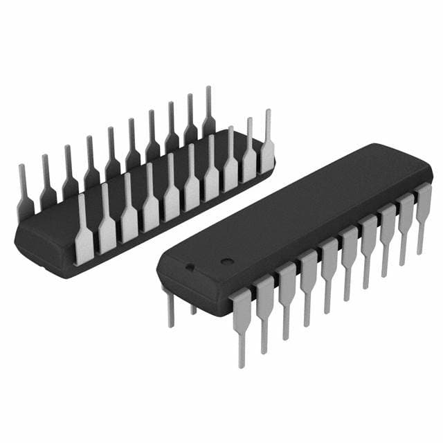
- Package: DIP (Dual In-line Package)
- Essence: The 74F540PC is a logic buffer IC that provides eight independent buffers with tri-state outputs. It is designed to amplify and drive signals in digital circuits.
- Packaging/Quantity: The 74F540PC is typically sold in tubes or trays containing multiple units.
Specifications
- Supply Voltage: 4.5V to 5.5V
- Logic Family: Fast CMOS (Complementary Metal-Oxide-Semiconductor)
- Number of Buffers: 8
- Output Type: Tri-State
- Operating Temperature Range: -40°C to +85°C
- Propagation Delay: 6 ns (typical)
Detailed Pin Configuration
The 74F540PC has a 20-pin Dual In-line Package (DIP). The pin configuration is as follows:
+---+--+---+
   A1 -|1  +--+ 20|- VCC
   B1 -|2         |- A2
   C1 -|3         |- B2
   D1 -|4         |- C2
   E1 -|5         |- D2
   F1 -|6         |- E2
   G1 -|7         |- F2
  GND -|8         |- G2
   Y1 -|9         |- H2
   Y2 -|10        |- Y3
   H1 -|11        |- Y4
   NC -|12        |- H4
   NC -|13        |- Y5
   NC -|14        |- Y6
   NC -|15        |- H6
   NC -|16        |- Y7
   NC -|17        |- Y8
   NC -|18        |- H8
   A3 -|19        |- B3
  VCC -|20        |- C3
       +----------+
Functional Features
- The 74F540PC provides eight independent buffers, allowing it to drive multiple signals simultaneously.
- It features tri-state outputs, which enable the buffers to be effectively disconnected from the circuit when not in use.
- The IC operates at high speed, making it suitable for applications that require fast signal amplification and driving.
Advantages and Disadvantages
Advantages: - High-speed operation - Tri-state outputs for effective signal isolation - Multiple independent buffers for simultaneous signal driving
Disadvantages: - Limited voltage supply range (4.5V to 5.5V) - Propagation delay of 6 ns may not be suitable for ultra-high-speed applications
Working Principles
The 74F540PC operates based on CMOS technology. It uses a combination of transistors and logic gates to amplify and drive digital signals. When an input signal is received, the internal circuitry amplifies it and drives the corresponding output buffer. The tri-state outputs allow the buffers to be enabled or disabled, providing flexibility in controlling the signal flow.
Detailed Application Field Plans
The 74F540PC is commonly used in various digital systems and applications, including:
- Microprocessor-based systems
- Data communication equipment
- Memory interfaces
- Bus drivers
- Address decoding circuits
- Signal buffering in complex digital circuits
Detailed and Complete Alternative Models
Some alternative models that offer similar functionality to the 74F540PC include:
- 74LS540: Low-power Schottky version with similar pin configuration and characteristics.
- 74HC540: High-speed CMOS version with improved voltage supply range and lower power consumption.
- SN54F540: Texas Instruments' equivalent IC with comparable specifications.
These alternative models can be considered based on specific requirements, availability, and compatibility with existing circuit designs.
Word count: 452 words
Lista 10 Vanliga frågor och svar relaterade till tillämpningen av 74F540PC i tekniska lösningar
Sure! Here are 10 common questions and answers related to the application of 74F540PC in technical solutions:
Q: What is the 74F540PC? A: The 74F540PC is a type of octal buffer/line driver integrated circuit (IC) that can be used in various digital logic applications.
Q: What is the purpose of the 74F540PC? A: The 74F540PC is designed to provide buffering and line driving capabilities, allowing it to interface between different logic families or devices with different voltage levels.
Q: What is the maximum operating voltage for the 74F540PC? A: The 74F540PC has a maximum operating voltage of 5.5 volts.
Q: How many input/output pins does the 74F540PC have? A: The 74F540PC has a total of 20 pins, with 8 input pins and 8 output pins.
Q: Can the 74F540PC handle bidirectional data transfer? A: Yes, the 74F540PC supports bidirectional data transfer, making it suitable for applications where data needs to be both sent and received.
Q: What is the maximum current that the 74F540PC can source/sink? A: The 74F540PC can source or sink up to 15 mA of current per output pin.
Q: Is the 74F540PC compatible with TTL logic levels? A: Yes, the 74F540PC is compatible with TTL logic levels, making it suitable for interfacing with TTL-based devices.
Q: Can the 74F540PC be used as a level shifter? A: Yes, the 74F540PC can be used as a level shifter to convert signals between different voltage levels.
Q: What is the typical propagation delay of the 74F540PC? A: The typical propagation delay of the 74F540PC is around 6 nanoseconds.
Q: Can the 74F540PC be cascaded to drive more than 8 outputs? A: Yes, multiple 74F540PC ICs can be cascaded together to drive more than 8 outputs, allowing for scalability in larger systems.
Please note that these answers are general and may vary depending on specific datasheet specifications or application requirements.