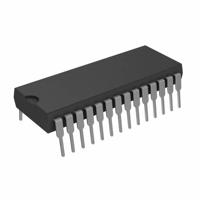
SCC2681AC1N28,112
Basic Information Overview
- Category: Integrated Circuit (IC)
- Use: Serial Communication Controller
- Characteristics:
- High-performance UART (Universal Asynchronous Receiver/Transmitter) with dual channels
- Supports asynchronous and synchronous serial communication protocols
- Operates at a maximum baud rate of 1.5 Mbps
- Package: 28-pin plastic shrink small outline package (SSOP)
- Essence: SCC2681AC1N28,112 is a versatile IC that enables reliable and efficient serial communication in various electronic devices.
- Packaging/Quantity: Available in reels, containing 2,500 units per reel.
Specifications
- Supply Voltage: 4.5V to 5.5V
- Operating Temperature Range: -40°C to +85°C
- Data Format: 8-bit data length, selectable parity bit, and stop bits
- FIFO Buffer Size: 16 bytes per channel
- Interrupts: Programmable interrupt sources for efficient data handling
- Clock Input: External clock source or internal oscillator
- Compatibility: TTL/CMOS compatible inputs and outputs
Detailed Pin Configuration
The SCC2681AC1N28,112 IC has a total of 28 pins. The pin configuration is as follows:
| Pin Number | Pin Name | Description | |------------|----------|-------------| | 1 | RDA | Receive Data A | | 2 | TDA | Transmit Data A | | 3 | CTS1 | Clear To Send 1 | | 4 | RTS1 | Request To Send 1 | | 5 | DCD1 | Data Carrier Detect 1 | | 6 | DSR1 | Data Set Ready 1 | | 7 | RI1 | Ring Indicator 1 | | 8 | GND | Ground | | 9 | VCC | Supply Voltage | | 10 | RDB | Receive Data B | | 11 | TDB | Transmit Data B | | 12 | CTS2 | Clear To Send 2 | | 13 | RTS2 | Request To Send 2 | | 14 | DCD2 | Data Carrier Detect 2 | | 15 | DSR2 | Data Set Ready 2 | | 16 | RI2 | Ring Indicator 2 | | 17-20 | NC | No Connection | | 21 | XTAL1 | External Clock Input 1 | | 22 | XTAL2 | External Clock Input 2 | | 23 | RESET | Reset Input | | 24 | INT/CLK | Interrupt Output/Clock Input | | 25 | RD1/WR | Read/Write Control for Channel A | | 26 | RD2/WR | Read/Write Control for Channel B | | 27 | CS1 | Chip Select for Channel A | | 28 | CS2 | Chip Select for Channel B |
Functional Features
- Dual-channel UART: Allows simultaneous communication on two independent channels.
- Programmable Baud Rate: Supports a wide range of baud rates for flexible communication requirements.
- FIFO Buffer: Provides efficient data buffering to minimize data loss and improve overall performance.
- Interrupt Support: Offers programmable interrupt sources for efficient handling of incoming and outgoing data.
- Auto Flow Control: Supports hardware flow control signals (CTS/RTS) for reliable data transmission.
Advantages and Disadvantages
Advantages: - Dual-channel capability enables parallel communication, increasing efficiency. - High-performance UART supports various communication protocols. - Programmable interrupt sources enhance data handling capabilities. - Auto flow control ensures reliable and error-free data transmission.
Disadvantages: - Limited buffer size (16 bytes per channel) may lead to data loss if not managed properly. - Requires external clock source or oscillator for operation.
Working Principles
The SCC2681AC1N28,112 is a serial communication controller that facilitates the exchange of data between electronic devices. It operates as a UART, which converts parallel data into serial format for transmission and vice versa. The IC supports both asynchronous and synchronous serial communication protocols.
The device consists of two independent channels, each with its own set of pins for data transmission and reception. It utilizes a FIFO buffer to store incoming and outgoing data, minimizing the risk of data loss. The programmable interrupt feature allows efficient handling of data, ensuring timely processing.
To establish communication, the SCC2681AC1N28,112 requires an external clock source or an internal oscillator. It supports various data formats, including selectable parity bits and stop bits, providing flexibility in data transmission.
Detailed Application Field Plans
The SCC2681AC
Lista 10 Vanliga frågor och svar relaterade till tillämpningen av SCC2681AC1N28,112 i tekniska lösningar
Sure! Here are 10 common questions and answers related to the application of SCC2681AC1N28,112 in technical solutions:
Q1: What is SCC2681AC1N28,112? A1: SCC2681AC1N28,112 is a UART (Universal Asynchronous Receiver/Transmitter) integrated circuit that provides serial communication capabilities in technical solutions.
Q2: What is the operating voltage range for SCC2681AC1N28,112? A2: The operating voltage range for SCC2681AC1N28,112 is typically between 4.5V and 5.5V.
Q3: What is the maximum data rate supported by SCC2681AC1N28,112? A3: SCC2681AC1N28,112 supports a maximum data rate of up to 1 Mbps.
Q4: Can SCC2681AC1N28,112 be used with both asynchronous and synchronous communication protocols? A4: Yes, SCC2681AC1N28,112 can be used with both asynchronous and synchronous communication protocols.
Q5: How many serial ports does SCC2681AC1N28,112 support? A5: SCC2681AC1N28,112 supports two independent serial ports.
Q6: Does SCC2681AC1N28,112 have built-in FIFO buffers? A6: Yes, SCC2681AC1N28,112 has built-in 16-byte receive and transmit FIFO buffers for each serial port.
Q7: Can SCC2681AC1N28,112 be used in both full-duplex and half-duplex communication modes? A7: Yes, SCC2681AC1N28,112 can be used in both full-duplex and half-duplex communication modes.
Q8: What is the power consumption of SCC2681AC1N28,112? A8: The power consumption of SCC2681AC1N28,112 depends on various factors, but typically it consumes around 10-20 mA.
Q9: Is SCC2681AC1N28,112 compatible with TTL (Transistor-Transistor Logic) level signals? A9: Yes, SCC2681AC1N28,112 is compatible with TTL level signals.
Q10: Can SCC2681AC1N28,112 be used in industrial applications? A10: Yes, SCC2681AC1N28,112 can be used in a wide range of industrial applications due to its robustness and reliability.
Please note that these answers are general and may vary depending on specific implementation details. It's always recommended to refer to the datasheet and consult the manufacturer for accurate information.


