

PCA9540BGD,125
Product Overview
- Category: Integrated Circuit
- Use: I2C Multiplexer
- Characteristics: Low-voltage 4-channel I2C multiplexer with reset
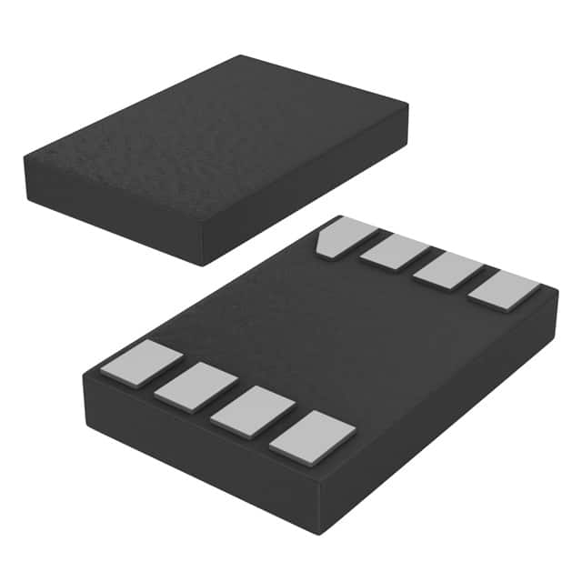
- Package: TSSOP16
- Essence: The PCA9540BGD,125 is a multiplexer that allows multiple I2C devices to share the same I2C bus. It provides a simple solution for expanding the number of I2C devices that can be connected to a microcontroller or other I2C master device.
- Packaging/Quantity: The PCA9540BGD,125 is typically sold in reels containing 2500 units.
Specifications
- Supply Voltage Range: 1.65V to 5.5V
- Number of Channels: 4
- I2C Bus Compatibility: Standard-mode, Fast-mode, Fast-mode Plus
- Reset Function: Yes
- Operating Temperature Range: -40°C to +85°C
Pin Configuration
The PCA9540BGD,125 has a total of 16 pins arranged as follows:
```
| | | 1 8 9 | | | | 16 15 14 | |___________________| ```
Pin Description:
- SCL0: I2C clock input/output for channel 0
- SDA0: I2C data input/output for channel 0
- GND: Ground
- SCL1: I2C clock input/output for channel 1
- SDA1: I2C data input/output for channel 1
- VCC: Power supply voltage
- RESET: Active-low reset input
- SCL2: I2C clock input/output for channel 2
- SDA2: I2C data input/output for channel 2
- NC: No connection
- SCL3: I2C clock input/output for channel 3
- SDA3: I2C data input/output for channel 3
- A0: Address selection bit 0
- A1: Address selection bit 1
- A2: Address selection bit 2
- GND: Ground
Functional Features
- Allows multiple I2C devices to share the same I2C bus
- Supports standard-mode, fast-mode, and fast-mode plus I2C bus compatibility
- Provides a reset function for all channels
- Low-voltage operation allows compatibility with a wide range of microcontrollers and other I2C master devices
Advantages and Disadvantages
Advantages: - Enables efficient utilization of the limited number of I2C bus pins on microcontrollers - Simplifies I2C bus management in systems with multiple I2C devices - Low-voltage operation enhances compatibility
Disadvantages: - Requires additional control logic to select the desired channel - Limited to 4 channels, may not be suitable for systems with a large number of I2C devices
Working Principles
The PCA9540BGD,125 operates by selectively connecting one of its four I2C channels to the shared I2C bus. The desired channel is selected using the address selection bits (A0, A1, A2). When a channel is selected, the corresponding SCL and SDA pins are connected to the I2C bus, allowing communication with the devices connected to that channel. The reset function can be used to reset all channels simultaneously.
Detailed Application Field Plans
The PCA9540BGD,125 finds applications in various scenarios where multiple I2C devices need to be connected to a single I2C bus. Some potential application fields include:
- Sensor Networks: In sensor networks, multiple sensors can be connected to the same I2C bus using the PCA9540BGD,125, simplifying the wiring and reducing the number of required I2C pins on the microcontroller.
- Industrial Control Systems: The PCA9540BGD,125 can be used in industrial control systems to connect multiple I2C-based control modules to a central controller, enabling efficient communication between different modules.
- Embedded Systems: In embedded systems, where space is often limited, the PCA9540BGD,125 allows for the expansion of I2C device connectivity without requiring additional I2C buses or microcontrollers.
Detailed and Complete Alternative Models
Some alternative models that offer similar functionality to the PCA9540BGD,125 are:
- PCA9541PW,112: 2-channel I2C multiplexer with reset
- PCA9542APW,118: 4-channel I2C multiplexer without reset
- TCA9548APWR: 8-channel I2C
Lista 10 Vanliga frågor och svar relaterade till tillämpningen av PCA9540BGD,125 i tekniska lösningar
Sure! Here are 10 common questions and answers related to the application of PCA9540BGD,125:
Q: What is PCA9540BGD,125? A: PCA9540BGD,125 is a multiplexer/demultiplexer IC (Integrated Circuit) that allows multiple I2C devices to share the same I2C bus.
Q: How does PCA9540BGD,125 work? A: PCA9540BGD,125 has four channels that can be individually selected to connect one of the I2C buses to the common I2C bus. It uses control registers to enable or disable each channel.
Q: What are the typical applications of PCA9540BGD,125? A: PCA9540BGD,125 is commonly used in systems where multiple I2C devices need to communicate with a single microcontroller or host device. It is often used in complex sensor networks, industrial automation, and IoT applications.
Q: How many I2C buses can PCA9540BGD,125 handle? A: PCA9540BGD,125 can handle up to four I2C buses.
Q: Can PCA9540BGD,125 be cascaded to support more than four I2C buses? A: Yes, multiple PCA9540BGD,125 ICs can be cascaded together to support more than four I2C buses.
Q: What is the maximum data rate supported by PCA9540BGD,125? A: PCA9540BGD,125 supports a maximum data rate of 400 kbps.
Q: How do I select a specific I2C bus using PCA9540BGD,125? A: You can select a specific I2C bus by writing the appropriate control bits to the control registers of PCA9540BGD,125.
Q: Can PCA9540BGD,125 be used with 3.3V and 5V systems? A: Yes, PCA9540BGD,125 is compatible with both 3.3V and 5V systems.
Q: Does PCA9540BGD,125 require external pull-up resistors for the I2C bus? A: Yes, external pull-up resistors are required for the I2C bus connected to PCA9540BGD,125.
Q: Are there any limitations or considerations when using PCA9540BGD,125? A: One limitation is that PCA9540BGD,125 does not support clock stretching. Additionally, care should be taken to avoid bus contention when multiple devices try to access the same I2C bus simultaneously.
Please note that these answers are general and may vary depending on the specific application and requirements. It is always recommended to refer to the datasheet and application notes provided by the manufacturer for detailed information.