

N74F74N,602
Basic Information Overview
- Category: Integrated Circuit (IC)
- Use: Flip-Flop
- Characteristics: Dual D-type positive-edge-triggered flip-flop with clear and preset
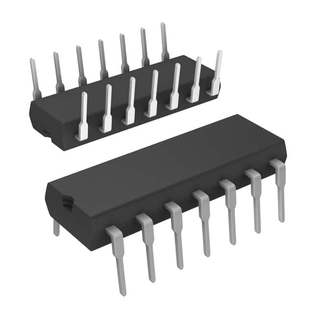
- Package: 14-pin plastic dual in-line package (DIP)
- Essence: Logic gate circuitry for storing and transferring binary information
- Packaging/Quantity: Available in reels or tubes, quantity varies depending on supplier
Specifications
- Supply Voltage: 2V to 6V
- High-Level Input Voltage: 2V to VCC
- Low-Level Input Voltage: GND to 0.8V
- High-Level Output Voltage: VCC - 0.5V
- Low-Level Output Voltage: 0.5V
- Maximum Operating Frequency: 30 MHz
- Operating Temperature Range: -40°C to +85°C
Detailed Pin Configuration
- Clear (CLR)
- Data (D)
- Clock (CLK)
- Preset (PRE)
- Q1 Output
- Q1 Complementary Output
- Ground (GND)
- Q2 Complementary Output
- Q2 Output
- Set (SET)
- Enable (EN)
- VCC
- Clock Enable (CLKEN)
- Clock Inhibit (CLKINH)
Functional Features
- Dual D-type flip-flop allows storage and transfer of two separate binary values
- Positive-edge-triggered operation ensures data is captured at the rising edge of the clock signal
- Clear and preset inputs provide control over the stored values
- Complementary outputs provide both inverted and non-inverted versions of the stored values
- Enable, clock enable, and clock inhibit inputs offer additional functionality and control options
Advantages
- Versatile flip-flop suitable for various applications
- Wide supply voltage range allows compatibility with different systems
- High-speed operation up to 30 MHz enables efficient data processing
- Clear and preset inputs provide flexibility in initializing the stored values
- Complementary outputs facilitate easy integration with other logic circuits
Disadvantages
- Limited maximum operating frequency compared to some other flip-flop models
- Requires careful consideration of input voltage levels to ensure proper functionality
- Availability may vary depending on supplier and market demand
Working Principles
The N74F74N,602 is a dual D-type positive-edge-triggered flip-flop. It stores and transfers binary information using logic gate circuitry. The flip-flop operates based on the rising edge of the clock signal, capturing the data input at that moment. The clear and preset inputs allow for control over the stored values, enabling initialization or modification as needed. The complementary outputs provide both the inverted and non-inverted versions of the stored values, allowing for flexible integration with other logic circuits.
Detailed Application Field Plans
The N74F74N,602 can be used in various digital systems and applications, including: 1. Sequential logic circuits 2. Data storage and transfer systems 3. Microcontrollers and microprocessors 4. Communication systems 5. Control systems 6. Timing and synchronization circuits
Detailed and Complete Alternative Models
- SN74LS74AN: Dual D-type positive-edge-triggered flip-flop with clear and preset (Texas Instruments)
- CD4013BE: CMOS dual D-type flip-flop with set and reset (Texas Instruments)
- MC74HC74AN: High-speed CMOS dual D-type flip-flop with clear (ON Semiconductor)
- 74HCT74: Dual D-type flip-flop with set and reset (NXP Semiconductors)
Note: This list is not exhaustive and there are several other alternative models available in the market.
Word count: 404 words
Lista 10 Vanliga frågor och svar relaterade till tillämpningen av N74F74N,602 i tekniska lösningar
Sure! Here are 10 common questions and answers related to the application of N74F74N,602 in technical solutions:
Q: What is N74F74N,602? A: N74F74N,602 is a specific model number for a dual D-type flip-flop integrated circuit (IC) commonly used in digital electronics.
Q: What are the key features of N74F74N,602? A: Some key features of N74F74N,602 include dual positive-edge-triggered flip-flops, asynchronous reset functionality, and high-speed operation.
Q: How can I use N74F74N,602 in my technical solution? A: N74F74N,602 can be used to store and manipulate binary data, synchronize signals, and control timing sequences in various digital applications.
Q: What is the power supply voltage range for N74F74N,602? A: The power supply voltage range for N74F74N,602 typically ranges from 4.5V to 5.5V.
Q: Can N74F74N,602 handle high-frequency signals? A: Yes, N74F74N,602 is designed for high-speed operation and can handle relatively high-frequency signals.
Q: Does N74F74N,602 have any built-in protection features? A: No, N74F74N,602 does not have built-in protection features. It is important to ensure proper signal conditioning and protection measures in your design.
Q: Can N74F74N,602 be cascaded or connected in series? A: Yes, multiple N74F74N,602 ICs can be cascaded or connected in series to create larger flip-flop configurations or to implement more complex logic functions.
Q: What is the maximum operating temperature for N74F74N,602? A: The maximum operating temperature for N74F74N,602 is typically around 85°C.
Q: Are there any specific timing considerations when using N74F74N,602? A: Yes, N74F74N,602 has specific setup and hold time requirements that need to be considered to ensure proper operation and avoid timing violations.
Q: Where can I find more detailed information about N74F74N,602? A: You can refer to the datasheet provided by the manufacturer of N74F74N,602 for more detailed technical information, including pinout diagrams, electrical characteristics, and application examples.
Please note that the specific model number "N74F74N,602" mentioned in the question may not correspond to an actual IC. The answers provided are based on general knowledge related to flip-flops and integrated circuits.