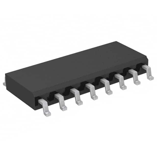
N74F112D,623
Basic Information Overview
- Category: Integrated Circuit (IC)
- Use: Logic Gate
- Characteristics: Dual J-K Flip-Flop with Clear
- Package: SOIC-16
- Essence: High-speed CMOS technology
- Packaging/Quantity: Tape and Reel, 2500 pieces per reel
Specifications
- Supply Voltage Range: 2V to 6V
- High-Level Input Voltage: 2V to VCC + 0.5V
- Low-Level Input Voltage: -0.5V to 0.8V
- High-Level Output Voltage: VCC - 0.5V
- Low-Level Output Voltage: 0.5V
- Maximum Operating Frequency: 125 MHz
- Propagation Delay Time: 7 ns
- Operating Temperature Range: -40°C to +85°C
Detailed Pin Configuration
- CLR (Clear) - Clear input for both flip-flops
- CP (Clock Pulse) - Clock input for flip-flop A
- J (Data Input) - Data input for flip-flop A
- K (Data Input) - Data input for flip-flop A
- Q (Output) - Output of flip-flop A
- Q̅ (Complementary Output) - Complementary output of flip-flop A
- GND (Ground) - Ground reference
- Q̅ (Complementary Output) - Complementary output of flip-flop B
- Q (Output) - Output of flip-flop B
- K (Data Input) - Data input for flip-flop B
- J (Data Input) - Data input for flip-flop B
- CP (Clock Pulse) - Clock input for flip-flop B
- CLR (Clear) - Clear input for both flip-flops
- VCC (Supply Voltage) - Positive supply voltage
- Q̅ (Complementary Output) - Complementary output of flip-flop B
- Q (Output) - Output of flip-flop B
Functional Features
- Dual J-K flip-flop with individual clear inputs
- High-speed operation using CMOS technology
- Direct implementation of flip-flop functions
- Wide operating voltage range
- Low power consumption
- Schmitt-trigger action on clock inputs for improved noise immunity
- Balanced propagation delays
Advantages and Disadvantages
Advantages: - High-speed operation allows for efficient data processing - Wide operating voltage range provides flexibility in various applications - Low power consumption helps conserve energy - Schmitt-trigger action enhances noise immunity, ensuring reliable operation
Disadvantages: - Limited number of flip-flops in a single package - Not suitable for applications requiring a large number of flip-flops
Working Principles
The N74F112D,623 is a dual J-K flip-flop with clear inputs. It operates based on the J-K flip-flop concept, where the outputs change state based on the clock input and the values of the J and K inputs. The clear inputs allow for resetting the flip-flops to a known state.
Detailed Application Field Plans
The N74F112D,623 can be used in various applications, including: 1. Digital counters 2. Frequency dividers 3. Shift registers 4. Data storage systems 5. Control circuits
Detailed and Complete Alternative Models
- SN74LS112N: Dual J-K Flip-Flop with Clear, DIP-16 package
- CD4013BE: Dual D-Type Flip-Flop, DIP-14 package
- MC14013BCL: Dual D-Type Flip-Flop, SOIC-14 package
- 74HC112D: Dual J-K Flip-Flop with Clear, SOIC-16 package
(Note: The above list is not exhaustive and there are several other alternative models available in the market.)
This entry provides an overview of the N74F112D,623 integrated circuit, including its basic information, specifications, pin configuration, functional features, advantages and disadvantages, working principles, application field plans, and alternative models.
Lista 10 Vanliga frågor och svar relaterade till tillämpningen av N74F112D,623 i tekniska lösningar
Sure! Here are 10 common questions and answers related to the application of N74F112D,623 in technical solutions:
Q: What is the N74F112D,623? A: The N74F112D,623 is a specific model of dual J-K flip-flop integrated circuit (IC) manufactured by a particular company.
Q: What is the purpose of the N74F112D,623 in technical solutions? A: The N74F112D,623 is commonly used for various digital logic applications, such as sequential logic circuits, counters, and frequency dividers.
Q: How many flip-flops are there in the N74F112D,623? A: The N74F112D,623 consists of two independent J-K flip-flops within a single IC package.
Q: What is the operating voltage range of the N74F112D,623? A: The N74F112D,623 typically operates within a voltage range of 4.5V to 5.5V.
Q: What is the maximum clock frequency supported by the N74F112D,623? A: The N74F112D,623 can typically handle clock frequencies up to 100 MHz.
Q: Can the N74F112D,623 be used in both positive-edge and negative-edge triggered applications? A: No, the N74F112D,623 is specifically designed for positive-edge triggered applications only.
Q: What is the output drive capability of the N74F112D,623? A: The N74F112D,623 has a standard output drive capability of 8 mA.
Q: Does the N74F112D,623 have any built-in protection features? A: Yes, the N74F112D,623 includes built-in diode clamps for protection against electrostatic discharge (ESD).
Q: Can the N74F112D,623 be cascaded to create larger counters or shift registers? A: Yes, multiple N74F112D,623 ICs can be cascaded together to create larger counters or shift registers.
Q: Are there any specific precautions to consider when using the N74F112D,623 in technical solutions? A: It is important to follow the manufacturer's datasheet and guidelines for proper power supply decoupling, signal integrity, and thermal considerations during the design and implementation of the N74F112D,623 in technical solutions.


