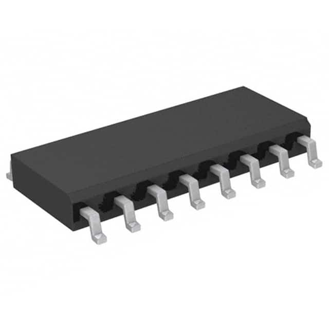
HEC4027BT,112
Basic Information Overview
- Category: Integrated Circuit (IC)
- Use: Digital Logic
- Characteristics: Dual J-K Flip-Flop with Set and Reset
- Package: SOIC-16
- Essence: Sequential Logic
- Packaging/Quantity: Tape and Reel, 2500 units per reel
Specifications
- Supply Voltage Range: 3V to 18V
- High-Level Input Voltage: 2V
- Low-Level Input Voltage: 0.8V
- High-Level Output Voltage: 4.5V
- Low-Level Output Voltage: 0.5V
- Maximum Operating Frequency: 25MHz
- Propagation Delay Time: 60ns
- Operating Temperature Range: -40°C to +85°C
Detailed Pin Configuration
- Clock Input (CP1)
- Clock Input (CP2)
- Data Input (D1)
- Data Input (D2)
- Set Input (S1)
- Reset Input (R1)
- Output (Q1)
- Complementary Output (Q̅1)
- Output (Q2)
- Complementary Output (Q̅2)
- Ground (GND)
- Output Enable (OE)
- Data Input (D3)
- Data Input (D4)
- Set Input (S2)
- Reset Input (R2)
Functional Features
- Dual J-K flip-flop with individual set and reset inputs
- Positive-edge triggered clock inputs
- Asynchronous set and reset inputs for each flip-flop
- Buffered outputs for improved performance
- Output enable input for disabling the outputs
- Wide supply voltage range allows for versatile applications
Advantages
- Dual flip-flop design provides flexibility in sequential logic circuits
- Individual set and reset inputs allow for precise control over the flip-flop states
- Buffered outputs enhance signal integrity and drive capability
- Wide supply voltage range enables compatibility with various systems
Disadvantages
- Propagation delay time may limit the maximum operating frequency in certain applications
- Package size (SOIC-16) may require additional space on the circuit board compared to smaller packages
Working Principles
The HEC4027BT,112 is a dual J-K flip-flop integrated circuit. Each flip-flop has its own clock input (CP), data input (D), set input (S), and reset input (R). The flip-flops are positive-edge triggered, meaning they change state when a rising edge is detected on the clock input. The set and reset inputs asynchronously override the clocked operation, allowing for immediate changes in the flip-flop states. The buffered outputs (Q and Q̅) provide reliable logic levels and can drive external circuitry. The output enable input (OE) allows for disabling the outputs when necessary.
Detailed Application Field Plans
The HEC4027BT,112 is commonly used in various digital logic applications, including: 1. Counters and frequency dividers 2. Shift registers 3. State machines 4. Data storage and retrieval systems 5. Clock synchronization circuits
Detailed and Complete Alternative Models
- CD4027B: Similar dual J-K flip-flop IC with set and reset inputs, available in different package options.
- MC74HC4027: Dual J-K flip-flop IC with set and reset inputs, optimized for high-speed operation.
- SN74LS112: Dual J-K flip-flop IC with set and reset inputs, designed for low-power applications.
Note: This entry provides an overview of the HEC4027BT,112 integrated circuit. For more detailed information, please refer to the datasheet provided by the manufacturer.
Word Count: 345
Lista 10 Vanliga frågor och svar relaterade till tillämpningen av HEC4027BT,112 i tekniska lösningar
Sure! Here are 10 common questions and answers related to the application of HEC4027BT,112 in technical solutions:
Q: What is HEC4027BT,112? A: HEC4027BT,112 is a specific model number for a digital integrated circuit (IC) chip used in various technical applications.
Q: What is the function of HEC4027BT,112? A: HEC4027BT,112 is a dual J-K flip-flop IC that can be used for storing and manipulating binary data in electronic circuits.
Q: What voltage range does HEC4027BT,112 operate on? A: HEC4027BT,112 typically operates on a voltage range of 3V to 15V.
Q: How many flip-flops are there in HEC4027BT,112? A: HEC4027BT,112 contains two independent J-K flip-flops.
Q: Can HEC4027BT,112 be used in both digital and analog circuits? A: No, HEC4027BT,112 is specifically designed for digital circuit applications.
Q: What is the maximum clock frequency supported by HEC4027BT,112? A: The maximum clock frequency supported by HEC4027BT,112 is typically around 25 MHz.
Q: Are there any special considerations for power supply connections with HEC4027BT,112? A: Yes, it is important to ensure proper decoupling capacitors are used near the power supply pins to minimize noise and voltage fluctuations.
Q: Can HEC4027BT,112 be cascaded to create larger counters or shift registers? A: Yes, multiple HEC4027BT,112 ICs can be cascaded together to create larger counters or shift registers.
Q: What are the typical applications of HEC4027BT,112? A: HEC4027BT,112 is commonly used in digital clocks, frequency dividers, and other timing-related circuits.
Q: Is HEC4027BT,112 readily available in the market? A: Availability may vary, but HEC4027BT,112 can usually be purchased from electronic component suppliers or distributors.
Please note that the specific details and answers may vary depending on the manufacturer's specifications and application requirements.


