

74LVTH574PW,118
Basic Information Overview
- Category: Integrated Circuit (IC)
- Use: Flip-Flop
- Characteristics: High-speed, low-power, octal D-type flip-flop with 3-state outputs
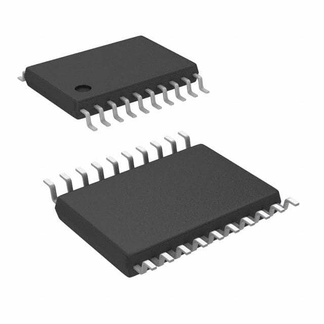
- Package: TSSOP (Thin Shrink Small Outline Package)
- Essence: This IC is a versatile flip-flop that can store and transfer data in electronic circuits.
- Packaging/Quantity: Available in reels of 2,500 pieces
Specifications
- Supply Voltage Range: 1.65V to 5.5V
- High-Speed Operation: 4.8 ns maximum propagation delay
- Low Power Consumption: ICC = 4 μA maximum
- Output Drive Capability: ±24 mA at 3.0V
- Operating Temperature Range: -40°C to +85°C
Detailed Pin Configuration
The 74LVTH574PW,118 IC has a total of 20 pins arranged as follows:
+----+--+----+
   OE --|1   +--+ 20|-- VCC
  D0 --|2         19|-- D7
  D1 --|3         18|-- Q7
  D2 --|4         17|-- Q6
  D3 --|5         16|-- Q5
  D4 --|6         15|-- Q4
  D5 --|7         14|-- Q3
  D6 --|8         13|-- Q2
 GND --|9         12|-- Q1
 CLK --|10        11|-- Q0
        +-----------+
Functional Features
- Octal D-Type Flip-Flop: The IC consists of eight individual D-type flip-flops with 3-state outputs.
- High-Speed Operation: It offers fast data transfer with a maximum propagation delay of 4.8 ns.
- Low Power Consumption: The IC consumes minimal power, making it suitable for battery-powered devices.
- 3-State Outputs: The outputs can be put in a high-impedance state, allowing multiple devices to share a common bus.
Advantages and Disadvantages
Advantages: - High-speed operation enables efficient data processing. - Low power consumption prolongs battery life in portable devices. - 3-state outputs facilitate bus sharing in complex systems.
Disadvantages: - Limited output drive capability may not be suitable for high-current applications. - TSSOP package may require careful handling during assembly.
Working Principles
The 74LVTH574PW,118 is a positive-edge-triggered flip-flop. It stores and transfers data based on the clock signal (CLK) input. When the CLK signal transitions from low to high, the data present at the D0-D7 inputs is latched and stored in the corresponding Q0-Q7 outputs. The outputs remain in this state until the next clock transition occurs.
Detailed Application Field Plans
The 74LVTH574PW,118 IC finds applications in various electronic systems, including: 1. Microprocessors and microcontrollers 2. Data storage and retrieval systems 3. Communication equipment 4. Industrial automation 5. Automotive electronics
Detailed and Complete Alternative Models
Some alternative models that offer similar functionality to the 74LVTH574PW,118 IC are: - SN74LVTH574PW,118 - MC74LVTH574PW,118 - 74LVTH574PW,112
Note: These alternative models may have slight differences in specifications or packaging options, but they serve the same purpose as the 74LVTH574PW,118 IC.
Word count: 346 words
Lista 10 Vanliga frågor och svar relaterade till tillämpningen av 74LVTH574PW,118 i tekniska lösningar
Sure! Here are 10 common questions and answers related to the application of 74LVTH574PW,118 in technical solutions:
Q: What is the function of the 74LVTH574PW,118? A: The 74LVTH574PW,118 is an octal D-type flip-flop with 3-state outputs. It can store and transfer data in digital circuits.
Q: What is the operating voltage range for the 74LVTH574PW,118? A: The operating voltage range for this IC is typically between 2.7V and 3.6V.
Q: How many flip-flops are there in the 74LVTH574PW,118? A: The 74LVTH574PW,118 contains 8 individual flip-flops, making it an octal flip-flop.
Q: What is the maximum clock frequency supported by the 74LVTH574PW,118? A: The maximum clock frequency supported by this IC is typically around 150 MHz.
Q: Can the 74LVTH574PW,118 be used in both synchronous and asynchronous applications? A: Yes, the 74LVTH574PW,118 can be used in both synchronous and asynchronous applications depending on the circuit requirements.
Q: What is the output drive strength of the 74LVTH574PW,118? A: The output drive strength of this IC is typically around 24 mA.
Q: Does the 74LVTH574PW,118 have internal pull-up or pull-down resistors? A: No, the 74LVTH574PW,118 does not have internal pull-up or pull-down resistors. External resistors may be required if needed.
Q: Can the 74LVTH574PW,118 be used in high-speed data transfer applications? A: Yes, the 74LVTH574PW,118 is designed for high-speed operation and can be used in high-speed data transfer applications.
Q: What is the power consumption of the 74LVTH574PW,118? A: The power consumption of this IC is typically low, making it suitable for battery-powered devices.
Q: Are there any specific precautions to consider when using the 74LVTH574PW,118? A: It is important to ensure proper decoupling capacitors are used near the power supply pins to minimize noise and voltage fluctuations. Additionally, care should be taken to avoid exceeding the maximum ratings specified in the datasheet.
Please note that the answers provided here are general and may vary depending on the specific application and circuit requirements. Always refer to the datasheet and consult with a qualified engineer for accurate information.