

74HCT299PW,118
Product Overview
Category
The 74HCT299PW,118 belongs to the category of integrated circuits (ICs).
Use
This IC is commonly used in digital electronics for data storage and manipulation.
Characteristics
- High-speed operation
- Low power consumption
- Wide operating voltage range
- Schmitt-trigger action on all inputs
- Buffered clock and direct clear inputs
- Output capability: standard
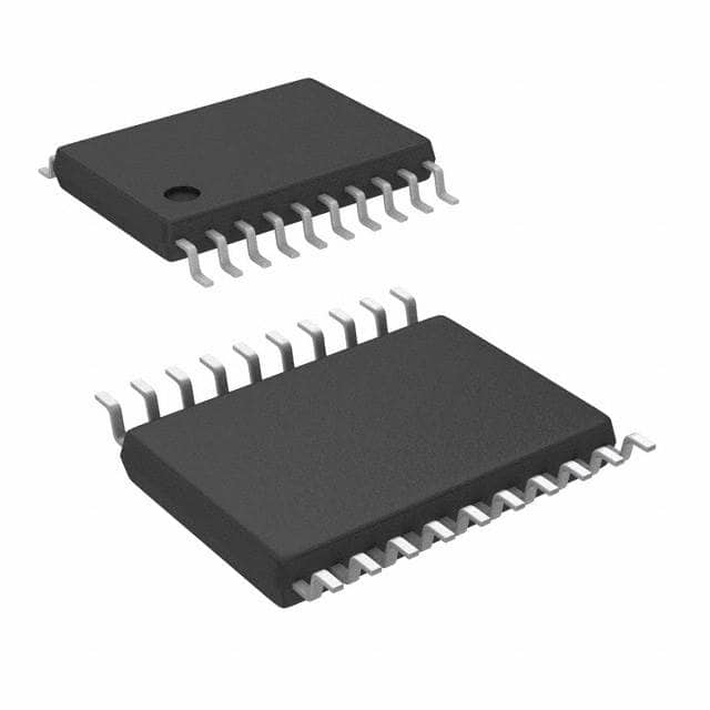
Package
The 74HCT299PW,118 is available in a TSSOP (Thin Shrink Small Outline Package) package.
Essence
The essence of this product lies in its ability to store and process digital data efficiently.
Packaging/Quantity
The 74HCT299PW,118 is typically packaged in reels or tubes, with a quantity of 2500 units per reel/tube.
Specifications
- Supply voltage: 2.0V to 6.0V
- Input voltage: -0.5V to VCC + 0.5V
- Output voltage: 0V to VCC
- Operating temperature range: -40°C to +125°C
- Input capacitance: 3.5pF
- Output capacitance: 6pF
- Propagation delay: 10ns
Detailed Pin Configuration
The 74HCT299PW,118 has a total of 20 pins, which are assigned specific functions as follows:
- Q0: Output pin 0
- Q1: Output pin 1
- Q2: Output pin 2
- Q3: Output pin 3
- Q4: Output pin 4
- Q5: Output pin 5
- Q6: Output pin 6
- Q7: Output pin 7
- GND: Ground
- CP: Clock pulse input
- DS: Serial data input
- MR: Master reset input
- OE: Output enable input
- SER: Serial data output
- QA: Output pin A
- QB: Output pin B
- QC: Output pin C
- QD: Output pin D
- VCC: Supply voltage
- QH: Output pin H
Functional Features
The 74HCT299PW,118 is a parallel-in/serial-out shift register with storage capability. It can be used to convert parallel data into serial data and vice versa. The IC has a clock input (CP) that controls the shifting of data, a master reset input (MR) for clearing the register, and an output enable input (OE) for enabling/disabling the outputs.
Advantages and Disadvantages
Advantages
- High-speed operation allows for efficient data processing.
- Low power consumption makes it suitable for battery-powered devices.
- Wide operating voltage range provides flexibility in various applications.
- Schmitt-trigger action on all inputs ensures reliable signal processing.
- Buffered clock and direct clear inputs simplify control.
Disadvantages
- Limited number of output pins may restrict certain applications requiring more outputs.
- TSSOP package may require careful handling during assembly.
Working Principles
The 74HCT299PW,118 operates based on the principles of digital logic circuits. It uses flip-flops to store and manipulate data. The clock input (CP) triggers the shifting of data through the register, while the master reset input (MR) clears the register to its initial state. The output enable input (OE) enables or disables the outputs, allowing for control over when the stored data is presented at the outputs.
Detailed Application Field Plans
The 74HCT299PW,118 finds applications in various fields, including: - Data communication systems - Microcontroller-based projects - Industrial automation - Instrumentation and measurement equipment - Consumer electronics
Detailed and Complete Alternative Models
Some alternative models that can be considered as alternatives to the 74HCT299PW,118 are: - SN74HC299N - CD74HCT299E - MC74HCT299N - 74HC299D
These models offer similar functionality and can be used interchangeably depending on availability and specific requirements.
In conclusion, the 74HCT299PW,118 is a versatile integrated circuit used for data storage and manipulation. Its high-speed operation, low power consumption, and wide operating voltage range make it suitable for various applications. However, its limited number of output pins and TSSOP package should be taken into consideration when selecting this IC for a particular project.
Lista 10 Vanliga frågor och svar relaterade till tillämpningen av 74HCT299PW,118 i tekniska lösningar
Sure! Here are 10 common questions and answers related to the application of 74HCT299PW,118 in technical solutions:
Q: What is the function of the 74HCT299PW,118? A: The 74HCT299PW,118 is an 8-bit universal shift register with parallel inputs and outputs.
Q: What is the operating voltage range for the 74HCT299PW,118? A: The operating voltage range for this IC is typically between 4.5V and 5.5V.
Q: Can the 74HCT299PW,118 be used as a bidirectional shift register? A: No, the 74HCT299PW,118 is a unidirectional shift register and can only shift data in one direction.
Q: How many parallel inputs does the 74HCT299PW,118 have? A: This IC has 8 parallel inputs, allowing you to load data into the shift register.
Q: What is the maximum clock frequency for the 74HCT299PW,118? A: The maximum clock frequency for this IC is typically around 80 MHz.
Q: Can the 74HCT299PW,118 be cascaded to create larger shift registers? A: Yes, multiple 74HCT299PW,118 ICs can be cascaded together to create larger shift registers.
Q: Does the 74HCT299PW,118 have any built-in latches? A: Yes, this IC has a latch enable input that allows you to latch the current data in the shift register.
Q: What is the power consumption of the 74HCT299PW,118? A: The power consumption of this IC is typically low, making it suitable for battery-powered applications.
Q: Can the 74HCT299PW,118 be used in both synchronous and asynchronous modes? A: Yes, this IC can operate in both synchronous and asynchronous modes, depending on the clock input.
Q: What are some common applications of the 74HCT299PW,118? A: Some common applications include data storage, serial-to-parallel conversion, parallel-to-serial conversion, and shift register-based control systems.
Please note that the answers provided here are general and may vary depending on specific datasheet specifications and application requirements.