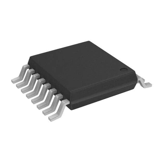
74LV4053PW,118
Basic Information Overview
- Category: Integrated Circuit (IC)
- Use: Multiplexer/Demultiplexer
- Characteristics: Low-voltage, triple 2-channel analog multiplexer/demultiplexer
- Package: TSSOP (Thin Shrink Small Outline Package)
- Essence: Analog Switch
- Packaging/Quantity: Tape and Reel, 2500 pieces per reel
Specifications
- Supply Voltage Range: 1.65V to 5.5V
- On-state Resistance: 80Ω (typical) at VCC = 4.5V
- Channel-to-Channel Crosstalk: -70dB at f = 1MHz
- Input Capacitance: 6pF (typical)
- Operating Temperature Range: -40°C to +125°C
Detailed Pin Configuration
The 74LV4053PW,118 IC has a total of 16 pins arranged as follows:
___________
         |           |
   S1 --|1         16|-- VCC
   S2 --|2         15|-- S3
   S3 --|3         14|-- Y1
   GND --|4         13|-- Y2
   D1 --|5         12|-- Y3
   D2 --|6         11|-- Y4
   D3 --|7         10|-- Y5
   D4 --|8          9|-- Y6
         |___________|
Functional Features
- Triple 2-channel analog multiplexer/demultiplexer
- Wide supply voltage range allows compatibility with various systems
- Low on-state resistance ensures minimal signal distortion
- High channel-to-channel crosstalk rejection for accurate signal routing
- Low input capacitance minimizes loading effects on the signal source
Advantages and Disadvantages
Advantages
- Versatile multiplexer/demultiplexer for analog signal routing
- Wide supply voltage range allows integration into different systems
- Low on-state resistance ensures minimal signal distortion
- High channel-to-channel crosstalk rejection for accurate signal routing
Disadvantages
- Limited number of channels (6 channels in total)
- Not suitable for high-frequency applications due to limited bandwidth
Working Principles
The 74LV4053PW,118 is a CMOS analog switch that operates as a multiplexer or demultiplexer. It uses a combination of control signals (S1, S2, and S3) to select one of the input channels (D1-D4) and route it to the corresponding output channel (Y1-Y6). The low on-state resistance allows the selected channel to pass through with minimal signal distortion.
Detailed Application Field Plans
The 74LV4053PW,118 IC finds applications in various fields, including: 1. Audio and video signal routing in multimedia devices 2. Data acquisition systems for selecting different sensor inputs 3. Communication systems for signal switching between different channels 4. Test and measurement equipment for signal routing and switching 5. Industrial automation for controlling analog signals in different processes
Detailed and Complete Alternative Models
Some alternative models to the 74LV4053PW,118 IC are: 1. CD4053B: CMOS Triple 2-Channel Analog Multiplexer/Demultiplexer 2. 74HC4053: High-Speed CMOS Triple 2-Channel Analog Multiplexer/Demultiplexer 3. DG406: Precision CMOS Analog Multiplexers/Demultiplexers 4. MAX4617: Low-Voltage, Single-Supply, SPST Analog Switches
These alternative models offer similar functionality and can be used as replacements depending on specific requirements.
In conclusion, the 74LV4053PW,118 is a low-voltage triple 2-channel analog multiplexer/demultiplexer IC. It offers versatile signal routing capabilities with low distortion and high crosstalk rejection. With its wide supply voltage range, it can be integrated into various systems across different application fields.
Lista 10 Vanliga frågor och svar relaterade till tillämpningen av 74LV4053PW,118 i tekniska lösningar
Sure! Here are 10 common questions and answers related to the application of 74LV4053PW,118 in technical solutions:
Q: What is the function of the 74LV4053PW,118? A: The 74LV4053PW,118 is a triple 2-channel analog multiplexer/demultiplexer IC. It allows for the selection of one of three input channels to be routed to an output.
Q: What is the operating voltage range of the 74LV4053PW,118? A: The operating voltage range of the 74LV4053PW,118 is typically between 1.65V and 5.5V.
Q: How many input channels does the 74LV4053PW,118 have? A: The 74LV4053PW,118 has three input channels.
Q: Can the 74LV4053PW,118 handle both analog and digital signals? A: Yes, the 74LV4053PW,118 can handle both analog and digital signals.
Q: What is the maximum frequency at which the 74LV4053PW,118 can operate? A: The 74LV4053PW,118 can operate at frequencies up to 125 MHz.
Q: Does the 74LV4053PW,118 have built-in ESD protection? A: Yes, the 74LV4053PW,118 has built-in ESD protection on all pins.
Q: Can I use multiple 74LV4053PW,118 ICs together to increase the number of input channels? A: Yes, you can cascade multiple 74LV4053PW,118 ICs together to increase the number of input channels.
Q: What is the typical on-resistance of the 74LV4053PW,118? A: The typical on-resistance of the 74LV4053PW,118 is around 70 ohms.
Q: Can I use the 74LV4053PW,118 in battery-powered applications? A: Yes, the 74LV4053PW,118 can be used in battery-powered applications due to its low power consumption.
Q: Does the 74LV4053PW,118 have any special features for signal integrity? A: Yes, the 74LV4053PW,118 has a break-before-make switching action, which helps minimize signal distortion during channel switching.
Please note that these answers are general and may vary depending on specific datasheet specifications and application requirements.


