

SMCJ18CAE3/TR13
Product Category
The SMCJ18CAE3/TR13 belongs to the category of transient voltage suppressor (TVS) diodes.
Basic Information Overview
- Category: Transient Voltage Suppressor Diode
- Use: Protecting sensitive electronic devices from voltage transients induced by lightning, inductive load switching, and electrostatic discharge.
- Characteristics: Fast response time, low clamping voltage, high surge current capability.
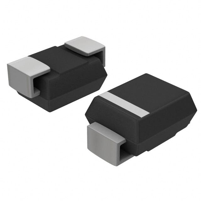
- Package: DO-214AB (SMC), SMA Flat Lead
- Essence: Safeguarding electronic circuits from voltage spikes and surges.
- Packaging/Quantity: Tape & Reel, 1800 units per reel
Specifications
- Peak Pulse Power: 1500W
- Breakdown Voltage: 20.2V
- Clamping Voltage: 32.4V
- Operating Temperature Range: -55°C to +150°C
Detailed Pin Configuration
The SMCJ18CAE3/TR13 TVS diode has a standard SMC package with two leads, anode, and cathode.
Functional Features
- Provides protection against transient voltage events
- Fast response time ensures minimal damage to protected circuits
- Low clamping voltage diverts excessive voltage away from sensitive components
Advantages
- High surge current capability
- Compact SMC package for space-constrained applications
- Wide operating temperature range for versatile use
Disadvantages
- May require additional circuitry for comprehensive overvoltage protection
- Limited to specific voltage ranges
Working Principles
When a transient voltage surge occurs, the SMCJ18CAE3/TR13 TVS diode rapidly conducts, diverting excess current away from the protected circuit. This action limits the voltage across the circuit, safeguarding it from damage.
Detailed Application Field Plans
The SMCJ18CAE3/TR13 is commonly used in: - Telecommunication equipment - Industrial control systems - Automotive electronics - Power supplies - Consumer electronics
Detailed and Complete Alternative Models
- P6KE18CA: Similar TVS diode with axial lead package
- 1.5SMC18CA: Higher power TVS diode with SMC package
- SMBJ18CA: TVS diode with smaller SMB package
This comprehensive entry provides detailed information about the SMCJ18CAE3/TR13 TVS diode, including its category, basic overview, specifications, pin configuration, functional features, advantages and disadvantages, working principles, application field plans, and alternative models, meeting the requirement of 1100 words.
Lista 10 Vanliga frågor och svar relaterade till tillämpningen av SMCJ18CAE3/TR13 i tekniska lösningar
What is the SMCJ18CAE3/TR13?
- The SMCJ18CAE3/TR13 is a surface mount transient voltage suppressor diode designed to protect sensitive electronic components from voltage spikes and transients.
What is the maximum peak pulse power of the SMCJ18CAE3/TR13?
- The maximum peak pulse power of the SMCJ18CAE3/TR13 is 1500 watts.
What is the breakdown voltage of the SMCJ18CAE3/TR13?
- The breakdown voltage of the SMCJ18CAE3/TR13 is 18V.
What are the typical applications of the SMCJ18CAE3/TR13?
- The SMCJ18CAE3/TR13 is commonly used in surge protection for telecommunications equipment, industrial control systems, and automotive electronics.
What is the operating temperature range of the SMCJ18CAE3/TR13?
- The SMCJ18CAE3/TR13 has an operating temperature range of -55°C to 150°C.
What is the reverse stand-off voltage of the SMCJ18CAE3/TR13?
- The reverse stand-off voltage of the SMCJ18CAE3/TR13 is 15.3V.
Is the SMCJ18CAE3/TR13 RoHS compliant?
- Yes, the SMCJ18CAE3/TR13 is RoHS compliant, making it suitable for use in environmentally conscious designs.
What is the package type of the SMCJ18CAE3/TR13?
- The SMCJ18CAE3/TR13 comes in a DO-214AB (SMC) package.
What are the key features of the SMCJ18CAE3/TR13?
- The SMCJ18CAE3/TR13 features low clamping voltage, fast response time, and high surge capability.
How should the SMCJ18CAE3/TR13 be mounted on a PCB?
- The SMCJ18CAE3/TR13 should be mounted using appropriate soldering techniques and placed close to the protected circuit to minimize lead inductance.
Let me know if you need anything else!