

SMBJ5382B/TR13
Product Overview
- Category: Electronic Component
- Use: Voltage Suppression in Electronic Circuits
- Characteristics: Fast response time, low clamping voltage, compact package
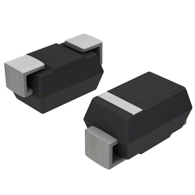
- Package: SMB (DO-214AA)
- Essence: Protects electronic circuits from voltage spikes
- Packaging/Quantity: Tape & Reel, 3000 units per reel
Specifications
- Peak Pulse Power: 5.0 kW
- Breakdown Voltage: 82 V
- Clamping Voltage: 135 V
- Operating Temperature Range: -55°C to +150°C
Detailed Pin Configuration
The SMBJ5382B/TR13 has two pins, with the following configuration: 1. Anode (A) 2. Cathode (K)
Functional Features
- Provides transient voltage suppression for sensitive electronics
- Fast response time ensures minimal damage to protected circuits
- Low clamping voltage limits voltage spikes to safe levels
Advantages and Disadvantages
Advantages
- Protects sensitive electronic components from voltage surges
- Compact size allows for easy integration into circuit designs
- Fast response time minimizes downtime due to circuit damage
Disadvantages
- May require additional components for comprehensive surge protection
- Clamping voltage may still be too high for some ultra-sensitive components
Working Principles
The SMBJ5382B/TR13 operates by diverting excess voltage away from sensitive electronic components, thereby preventing damage due to voltage spikes. When a surge occurs, the device rapidly conducts current to limit the voltage across the protected circuit.
Detailed Application Field Plans
This component is commonly used in various electronic devices and systems, including: - Power Supplies - Communication Equipment - Industrial Control Systems - Automotive Electronics - Consumer Electronics
Detailed and Complete Alternative Models
- SMBJ5.0A-58CA: Similar specifications, different breakdown voltage
- SMBJ5382B-TP: Through-hole mounting option, same specifications
- SMBJ5382B-E3/52: Different packaging format, same specifications
In conclusion, the SMBJ5382B/TR13 is a vital component for protecting electronic circuits from voltage surges, offering fast response times and low clamping voltages. Its compact size and wide operating temperature range make it suitable for various applications in different industries.
Word Count: 320
Lista 10 Vanliga frågor och svar relaterade till tillämpningen av SMBJ5382B/TR13 i tekniska lösningar
What is the SMBJ5382B/TR13?
- The SMBJ5382B/TR13 is a transient voltage suppressor diode designed to protect sensitive electronic components from voltage spikes and transients.
What is the maximum working voltage of the SMBJ5382B/TR13?
- The maximum working voltage of the SMBJ5382B/TR13 is 5.0V.
What is the peak pulse power dissipation of the SMBJ5382B/TR13?
- The peak pulse power dissipation of the SMBJ5382B/TR13 is 600W.
What are the typical applications of the SMBJ5382B/TR13?
- The SMBJ5382B/TR13 is commonly used in protection circuits for telecommunications equipment, industrial control systems, and automotive electronics.
What is the operating temperature range of the SMBJ5382B/TR13?
- The operating temperature range of the SMBJ5382B/TR13 is -55°C to +150°C.
What is the reverse stand-off voltage of the SMBJ5382B/TR13?
- The reverse stand-off voltage of the SMBJ5382B/TR13 is 5.0V.
Does the SMBJ5382B/TR13 meet any specific industry standards?
- Yes, the SMBJ5382B/TR13 complies with the requirements of RoHS and is also halogen-free.
What is the response time of the SMBJ5382B/TR13 to voltage transients?
- The response time of the SMBJ5382B/TR13 is very fast, typically responding within nanoseconds to clamp voltage spikes.
Can the SMBJ5382B/TR13 be used in high-frequency applications?
- Yes, the SMBJ5382B/TR13 is suitable for high-frequency applications due to its low capacitance and fast response time.
Are there any recommended layout considerations when using the SMBJ5382B/TR13?
- It is recommended to minimize the length of the traces between the SMBJ5382B/TR13 and the protected circuitry and to provide a low-impedance path to ground for optimal performance.