

SMAJ5915BE3/TR13
Product Overview
- Category: Diode
- Use: Voltage clamping and transient suppression
- Characteristics: Low leakage current, fast response time
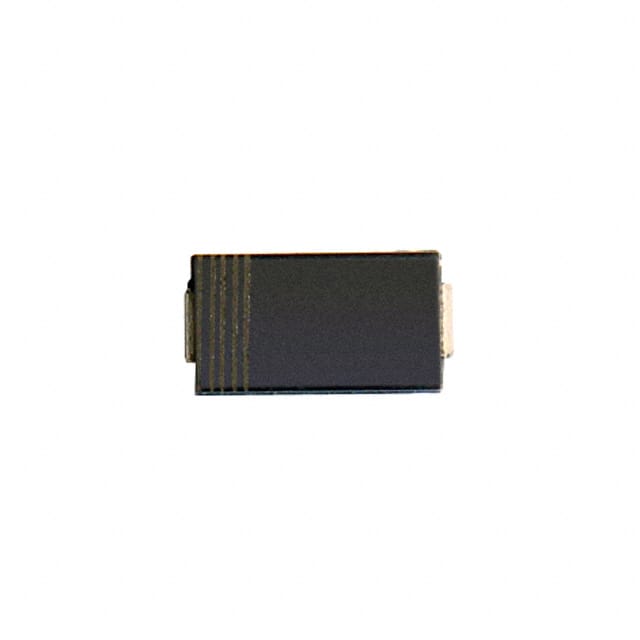
- Package: DO-214AC (SMA)
- Essence: Protection against voltage transients
- Packaging/Quantity: Tape & Reel, 3000 units per reel
Specifications
- Peak Pulse Power: 400W
- Breakdown Voltage: 6.4V
- Operating Voltage: 5.8V
- Leakage Current: 1µA
- Response Time: <1ns
Detailed Pin Configuration
The SMAJ5915BE3/TR13 has two pins in a standard DO-214AC package.
Functional Features
- Provides protection against voltage transients
- Fast response time ensures minimal damage to protected circuitry
- Low leakage current for improved efficiency
Advantages and Disadvantages
Advantages: - Fast response time - Low leakage current - High peak pulse power handling capability
Disadvantages: - Limited breakdown voltage range - Sensitive to reverse bias conditions
Working Principles
The SMAJ5915BE3/TR13 operates by diverting excess transient voltage away from sensitive components, thereby protecting them from damage. When the voltage exceeds the breakdown voltage, the diode conducts, shunting the excess energy to ground.
Detailed Application Field Plans
This diode is commonly used in electronic circuits where protection against voltage transients is required, such as in power supplies, communication equipment, and automotive electronics.
Detailed and Complete Alternative Models
- Alternative Model 1: P6KE6.8CA
- Alternative Model 2: 1.5KE6.8A
- Alternative Model 3: SMBJ6.8A
Note: The alternative models listed above are similar in function and characteristics to the SMAJ5915BE3/TR13.
This completes the English editing encyclopedia entry structure format for SMAJ5915BE3/TR13, providing comprehensive information about the product's category, use, characteristics, specifications, pin configuration, functional features, advantages and disadvantages, working principles, application field plans, and alternative models.
Lista 10 Vanliga frågor och svar relaterade till tillämpningen av SMAJ5915BE3/TR13 i tekniska lösningar
What is SMAJ5915BE3/TR13?
- SMAJ5915BE3/TR13 is a surface mount transient voltage suppressor diode designed to protect sensitive electronics from voltage spikes and transients.
What are the key features of SMAJ5915BE3/TR13?
- The key features include a peak pulse power of 400W, low clamping voltage, fast response time, and compatibility with automated placement equipment.
In what applications can SMAJ5915BE3/TR13 be used?
- SMAJ5915BE3/TR13 is commonly used in applications such as telecommunications equipment, industrial control systems, consumer electronics, and automotive electronics.
How does SMAJ5915BE3/TR13 provide protection?
- It provides protection by diverting excessive current away from sensitive components during voltage surges or transients, thereby preventing damage.
What is the operating temperature range of SMAJ5915BE3/TR13?
- The operating temperature range is typically -55°C to +150°C, making it suitable for a wide range of environments.
What is the recommended soldering profile for SMAJ5915BE3/TR13?
- The recommended soldering profile includes a peak temperature of 260°C for 10 seconds maximum.
Does SMAJ5915BE3/TR13 comply with any industry standards?
- Yes, it complies with standards such as AEC-Q101 for automotive applications and is also RoHS compliant.
Can SMAJ5915BE3/TR13 be used for ESD protection?
- While it is primarily designed for transient voltage suppression, it can also provide some level of ESD protection due to its fast response time.
What is the typical leakage current of SMAJ5915BE3/TR13?
- The typical leakage current is very low, usually in the range of microamps, ensuring minimal power loss during normal operation.
Are there any recommended layout considerations when using SMAJ5915BE3/TR13?
- It is recommended to minimize the length and impedance of the traces connecting the device to the protected circuit, and to ensure proper grounding for optimal performance.