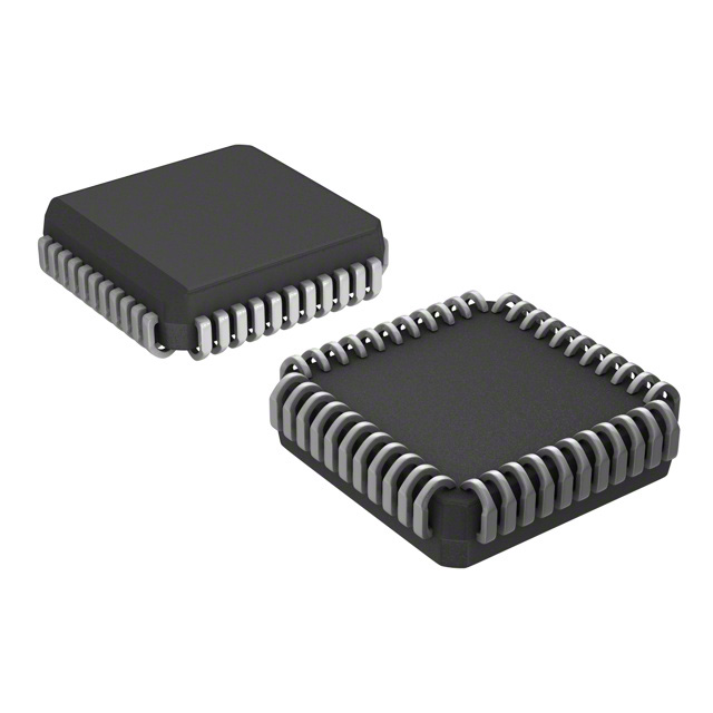
PIC16F877AT-I/L
Product Overview
Category
The PIC16F877AT-I/L belongs to the category of microcontrollers.
Use
This microcontroller is widely used in various electronic applications that require embedded control and processing capabilities.
Characteristics
- High-performance 8-bit RISC architecture
- Flash-based program memory
- Wide operating voltage range
- Low power consumption
- Enhanced peripheral integration
- Flexible I/O options
Package
The PIC16F877AT-I/L is available in a 44-pin LQFP (Low-Profile Quad Flat Package) package.
Essence
The essence of the PIC16F877AT-I/L lies in its ability to provide efficient and reliable control and processing capabilities for a wide range of electronic applications.
Packaging/Quantity
The PIC16F877AT-I/L is typically packaged in reels, with each reel containing a specific quantity of microcontrollers. The exact quantity may vary depending on the manufacturer's specifications.
Specifications
- Microcontroller Family: PIC16F
- Core Size: 8-bit
- Program Memory Size: 14KB
- RAM Size: 368B
- Number of I/O Pins: 33
- Operating Voltage Range: 2.0V to 5.5V
- Maximum CPU Speed: 20 MHz
- Data Bus Width: 8-bit
- ADC Resolution: 10-bit
- Number of Timers: 3
- Communication Interfaces: USART, SPI, I2C
Detailed Pin Configuration
The PIC16F877AT-I/L features a total of 44 pins, each serving a specific purpose. Here is a detailed pin configuration:
- VDD - Power supply voltage
- RA0 - General-purpose I/O pin
- RA1 - General-purpose I/O pin
- RA2 - General-purpose I/O pin
- RA3 - General-purpose I/O pin
- RA4/TOCKI - General-purpose I/O pin or Timer0 external clock input
- RA5/MCLR/VPP - Master Clear input or programming voltage supply
- VSS - Ground
- RB0/INT - General-purpose I/O pin or External Interrupt input
- RB1 - General-purpose I/O pin
- RB2 - General-purpose I/O pin
- RB3/PGM - General-purpose I/O pin or In-Circuit Serial Programming data pin
- RB4 - General-purpose I/O pin
- RB5 - General-purpose I/O pin
- RB6/PGC - General-purpose I/O pin or In-Circuit Serial Programming clock pin
- RB7/PGD - General-purpose I/O pin or In-Circuit Serial Programming data pin 17-33. RC0 to RC7 - General-purpose I/O pins
- RD0/RX - General-purpose I/O pin or USART receive pin
- RD1/TX - General-purpose I/O pin or USART transmit pin
- RD2/CCP2 - General-purpose I/O pin or Capture/Compare/PWM module 2 output
- RD3/CCP3 - General-purpose I/O pin or Capture/Compare/PWM module 3 output
- RD4/CCP4 - General-purpose I/O pin or Capture/Compare/PWM module 4 output
- RD5/CCP5 - General-purpose I/O pin or Capture/Compare/PWM module 5 output
- RD6/CCP6 - General-purpose I/O pin or Capture/Compare/PWM module 6 output
- RD7/CCP7 - General-purpose I/O pin or Capture/Compare/PWM module 7 output
- VSS - Ground
- VDD - Power supply voltage
- OSC1/CLKI - Oscillator input or external clock source input
Functional Features
The PIC16F877AT-I/L offers several functional features that enhance its performance and versatility:
- Flash program memory for easy reprogramming
- Enhanced peripheral integration, including timers, USART, SPI, and I2C interfaces
- Analog-to-Digital Converter (ADC) for precise analog signal measurements
- Capture/Compare/PWM modules for advanced control applications
- Low-power modes for efficient energy management
- Wide operating voltage range for compatibility with various power sources
- Flexible I/O options for seamless integration with external devices
Advantages and Disadvantages
Advantages
- High-performance RISC architecture ensures efficient execution of instructions
- Flash-based program memory allows for easy and quick updates
- Enhanced peripheral integration reduces the need for additional components
- Low power consumption extends battery life in portable applications
- Wide operating voltage range provides flexibility in different environments
Disadvantages
- Limited program memory size may restrict the complexity of applications
Lista 10 Vanliga frågor och svar relaterade till tillämpningen av PIC16F877AT-I/L i tekniska lösningar
What is the maximum operating frequency of PIC16F877AT-I/L?
- The maximum operating frequency of PIC16F877AT-I/L is 20 MHz.How many I/O pins does PIC16F877AT-I/L have?
- PIC16F877AT-I/L has a total of 33 I/O pins.What is the flash memory size of PIC16F877AT-I/L?
- The flash memory size of PIC16F877AT-I/L is 14 KB.Can PIC16F877AT-I/L be used for analog-to-digital conversion?
- Yes, PIC16F877AT-I/L has an integrated 10-bit ADC module.Does PIC16F877AT-I/L support serial communication protocols?
- Yes, PIC16F877AT-I/L supports USART, SPI, and I2C communication protocols.What are the power supply voltage requirements for PIC16F877AT-I/L?
- PIC16F877AT-I/L operates at a voltage range of 2.0V to 5.5V.Is PIC16F877AT-I/L suitable for battery-powered applications?
- Yes, PIC16F877AT-I/L's low power consumption makes it suitable for battery-powered applications.Can PIC16F877AT-I/L be programmed using C language?
- Yes, PIC16F877AT-I/L can be programmed using C language with appropriate compilers.What are the available timer modules in PIC16F877AT-I/L?
- PIC16F877AT-I/L has three timer modules: Timer0, Timer1, and Timer2.Is PIC16F877AT-I/L suitable for industrial control applications?
- Yes, PIC16F877AT-I/L is commonly used in industrial control applications due to its robust features and reliability.


