

MCP14E10-E/MF
Product Overview
Category
The MCP14E10-E/MF belongs to the category of integrated circuits (ICs).
Use
This IC is primarily used for driving MOSFETs and IGBTs in various applications.
Characteristics
- High-speed switching capability
- Low power consumption
- Wide operating voltage range
- Enhanced ESD protection
- Compact package size
Package
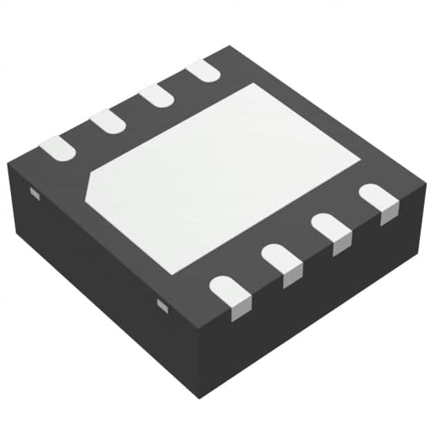
The MCP14E10-E/MF is available in a small outline package (SOIC) with 8 pins.
Essence
The essence of this product lies in its ability to efficiently drive power transistors, enabling precise control and high-performance switching.
Packaging/Quantity
The MCP14E10-E/MF is typically packaged in reels containing 2500 units per reel.
Specifications
- Supply Voltage: 4.5V to 18V
- Output Current: 4A (peak)
- Propagation Delay Time: 35ns (typical)
- Rise/Fall Time: 15ns (typical)
- Operating Temperature Range: -40°C to +125°C
Detailed Pin Configuration
- VDD: Power supply input
- IN: Input pin for controlling the output stage
- GND: Ground reference
- LO: Low-side output pin
- HO: High-side output pin
- NC: No connection
- SD: Shutdown input pin
- VSS: Negative power supply input
Functional Features
- High-speed gate driver
- Integrated bootstrap diode
- Under-voltage lockout (UVLO) protection
- Over-temperature protection
- Short-circuit protection
- Fault reporting output
Advantages and Disadvantages
Advantages
- Fast switching speed improves system efficiency
- Low power consumption reduces energy waste
- Wide operating voltage range enhances versatility
- Integrated protection features ensure system reliability
Disadvantages
- Limited output current may restrict certain high-power applications
- Non-isolated design requires additional safety measures in some scenarios
Working Principles
The MCP14E10-E/MF operates by receiving control signals at the input pin (IN) and generating corresponding gate drive signals at the output pins (LO and HO). These signals are used to control the switching of MOSFETs or IGBTs, allowing efficient power transfer in various applications.
Detailed Application Field Plans
The MCP14E10-E/MF finds extensive use in the following application fields:
- Motor control systems
- Power supplies
- Lighting systems
- Industrial automation
- Automotive electronics
Detailed and Complete Alternative Models
- MCP14E11-E/MF
- MCP14E12-E/MF
- MCP14E13-E/MF
- MCP14E14-E/MF
- MCP14E15-E/MF
These alternative models offer similar functionality and performance characteristics, providing flexibility for different design requirements.
In conclusion, the MCP14E10-E/MF is a high-performance gate driver IC that offers fast switching speed, low power consumption, and integrated protection features. It finds wide application in motor control, power supply, lighting, industrial automation, and automotive electronics. With its compact package size and comprehensive specifications, it provides an efficient solution for driving MOSFETs and IGBTs in various electronic systems.
Lista 10 Vanliga frågor och svar relaterade till tillämpningen av MCP14E10-E/MF i tekniska lösningar
What is the MCP14E10-E/MF used for?
- The MCP14E10-E/MF is a high-speed MOSFET driver designed to drive enhancement mode MOSFETs in various applications.
What is the maximum voltage rating of the MCP14E10-E/MF?
- The MCP14E10-E/MF has a maximum voltage rating of 18V.
What is the typical input threshold voltage of the MCP14E10-E/MF?
- The typical input threshold voltage of the MCP14E10-E/MF is 2.5V.
Can the MCP14E10-E/MF be used in automotive applications?
- Yes, the MCP14E10-E/MF is suitable for use in automotive applications.
What is the maximum output current of the MCP14E10-E/MF?
- The maximum output current of the MCP14E10-E/MF is 4A.
Is the MCP14E10-E/MF compatible with TTL and CMOS logic levels?
- Yes, the MCP14E10-E/MF is compatible with both TTL and CMOS logic levels.
What is the operating temperature range of the MCP14E10-E/MF?
- The operating temperature range of the MCP14E10-E/MF is -40°C to 125°C.
Does the MCP14E10-E/MF have built-in shoot-through protection?
- Yes, the MCP14E10-E/MF features built-in shoot-through protection.
Can the MCP14E10-E/MF be used in motor control applications?
- Yes, the MCP14E10-E/MF is suitable for use in motor control applications.
What package options are available for the MCP14E10-E/MF?
- The MCP14E10-E/MF is available in 8-lead PDIP, SOIC, and TSSOP packages.