

Q6010R5 Product Overview
Introduction
The Q6010R5 is a semiconductor device belonging to the category of power thyristors. This entry provides an overview of the basic information, specifications, pin configuration, functional features, advantages and disadvantages, working principles, application field plans, and alternative models of the Q6010R5.
Basic Information Overview
- Category: Power Thyristor
- Use: The Q6010R5 is commonly used in applications requiring high current and voltage control, such as motor drives, power supplies, and industrial equipment.
- Characteristics: It exhibits high surge capability, low on-state voltage, and high commutation capability.
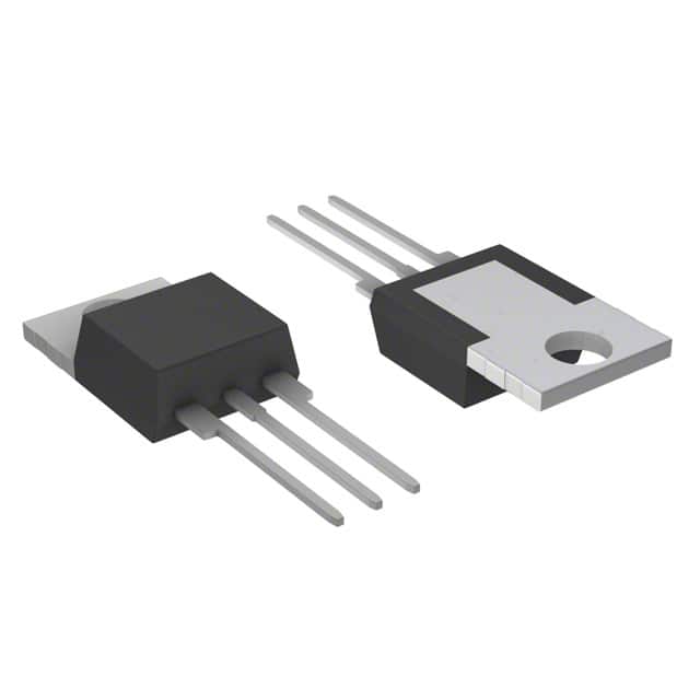
- Package: The Q6010R5 is typically available in a TO-220AB package.
- Essence: It is designed to provide reliable and efficient power control in various electronic systems.
- Packaging/Quantity: The Q6010R5 is usually packaged individually and is available in different quantities based on customer requirements.
Specifications
- Voltage Rating: 600V
- Current Rating: 10A
- Gate Trigger Current (Max): 25mA
- Gate Trigger Voltage (Max): 1.5V
- On-State Voltage (Max): 1.7V
- Repetitive Peak Off-State Voltage: 600V
- Operating Temperature Range: -40°C to 125°C
Detailed Pin Configuration
The Q6010R5 typically consists of three pins: Anode, Cathode, and Gate. The pin configuration is as follows: - Anode (A) - Cathode (K) - Gate (G)
Functional Features
- High Surge Capability
- Low On-State Voltage Drop
- High Commutation Capability
- Reliable Turn-On and Turn-Off Performance
Advantages and Disadvantages
Advantages
- High surge capability makes it suitable for demanding applications.
- Low on-state voltage drop reduces power dissipation.
- High commutation capability ensures efficient switching.
Disadvantages
- Sensitive to voltage and current transients.
- Requires careful consideration of gate drive circuitry for optimal performance.
Working Principles
The Q6010R5 operates based on the principle of controlling the flow of current by triggering the thyristor into conduction using the gate signal. Once triggered, it remains conducting until the current through it falls below a certain threshold or the voltage across it reverses.
Detailed Application Field Plans
The Q6010R5 finds extensive use in various applications, including: - Motor Drives - Power Supplies - Industrial Equipment - Lighting Control Systems - Heating Control Systems
Detailed and Complete Alternative Models
- Q6012R5
- Q6020R5
- Q6030R5
- Q6040R5
In conclusion, the Q6010R5 power thyristor offers high surge capability, low on-state voltage, and high commutation capability, making it suitable for diverse high-power applications. Its working principles, application field plans, and alternative models further enhance its versatility in the electronics industry.
Word Count: 410
Lista 10 Vanliga frågor och svar relaterade till tillämpningen av Q6010R5 i tekniska lösningar
What is Q6010R5?
- Q6010R5 is a high-power, solid-state relay designed for use in various technical solutions.
What are the key features of Q6010R5?
- The key features of Q6010R5 include high power handling capability, optically isolated control, and zero-crossing switching for reduced EMI.
What is the maximum load current and voltage rating of Q6010R5?
- Q6010R5 has a maximum load current rating of 10A and a maximum load voltage rating of 600V.
In what applications can Q6010R5 be used?
- Q6010R5 can be used in applications such as industrial automation, HVAC systems, lighting controls, and motor controls.
Is Q6010R5 suitable for resistive or inductive loads?
- Q6010R5 is suitable for both resistive and inductive loads, making it versatile for different types of equipment.
Does Q6010R5 support AC or DC input control signals?
- Q6010R5 supports AC input control signals, making it compatible with a wide range of control systems.
What is the typical response time of Q6010R5?
- The typical response time of Q6010R5 is in the range of microseconds, ensuring fast and precise switching.
Are there any built-in protection features in Q6010R5?
- Yes, Q6010R5 includes built-in overvoltage protection and snubber circuits for enhanced reliability and safety.
Can multiple Q6010R5 relays be synchronized for parallel operation?
- Yes, multiple Q6010R5 relays can be synchronized for parallel operation to handle higher power requirements.
What are the recommended thermal management practices for Q6010R5?
- It is recommended to use proper heat sinking and thermal insulation techniques to ensure optimal performance and longevity of Q6010R5 in high-power applications.