

IXST40N60B
Introduction
The IXST40N60B is a power semiconductor device belonging to the category of Insulated Gate Bipolar Transistors (IGBTs). This entry provides an overview of the basic information, specifications, pin configuration, functional features, advantages and disadvantages, working principles, application field plans, and alternative models of the IXST40N60B.
Basic Information Overview
- Category: Insulated Gate Bipolar Transistor (IGBT)
- Use: Power switching applications in various electronic devices and systems
- Characteristics: High voltage capability, low saturation voltage, fast switching speed
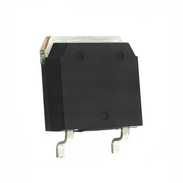
- Package: TO-247
- Essence: Power control and conversion
- Packaging/Quantity: Typically packaged individually, quantity varies based on manufacturer
Specifications
- Voltage Rating: 600V
- Current Rating: 40A
- Maximum Power Dissipation: 300W
- Operating Temperature Range: -55°C to 150°C
- Gate-Emitter Voltage: ±20V
- Collector-Emitter Saturation Voltage: 1.8V at 25°C, 3.0V at 150°C
Detailed Pin Configuration
The IXST40N60B typically has the following pin configuration: 1. Collector (C) 2. Gate (G) 3. Emitter (E)
Functional Features
- High voltage capability for power applications
- Low saturation voltage for reduced power losses
- Fast switching speed for efficient operation
Advantages and Disadvantages
Advantages
- High voltage rating suitable for power applications
- Low saturation voltage reduces power dissipation
- Fast switching speed enhances efficiency
Disadvantages
- Higher cost compared to other power transistors
- Sensitive to overvoltage conditions
Working Principles
The IXST40N60B operates based on the principles of controlling the flow of current between the collector and emitter terminals using the gate signal. When a suitable gate signal is applied, the IGBT allows current to flow, and when the gate signal is removed, the current flow ceases.
Detailed Application Field Plans
The IXST40N60B finds extensive use in various applications including: - Motor drives - Uninterruptible power supplies (UPS) - Renewable energy systems - Induction heating systems - Welding equipment
Detailed and Complete Alternative Models
Some alternative models to the IXST40N60B include: - IRG4PH40UD - FGA40N65SMD - STGW40NC60WD
In conclusion, the IXST40N60B is a high-performance IGBT with a wide range of applications in power electronics. Its unique combination of high voltage capability, low saturation voltage, and fast switching speed makes it a preferred choice for various power switching applications.
[Word Count: 410]
Lista 10 Vanliga frågor och svar relaterade till tillämpningen av IXST40N60B i tekniska lösningar
What is the maximum voltage rating of IXST40N60B?
- The maximum voltage rating of IXST40N60B is 600V.
What is the continuous drain current of IXST40N60B?
- The continuous drain current of IXST40N60B is 40A.
What type of package does IXST40N60B come in?
- IXST40N60B comes in a TO-247 package.
What is the typical on-state resistance of IXST40N60B?
- The typical on-state resistance of IXST40N60B is 0.15 ohms.
Can IXST40N60B be used for high-frequency switching applications?
- Yes, IXST40N60B is suitable for high-frequency switching applications.
Does IXST40N60B have built-in protection features?
- IXST40N60B does not have built-in protection features and may require external circuitry for protection.
What is the operating temperature range of IXST40N60B?
- The operating temperature range of IXST40N60B is -55°C to 150°C.
Is IXST40N60B RoHS compliant?
- Yes, IXST40N60B is RoHS compliant.
What are some common applications for IXST40N60B?
- Common applications for IXST40N60B include motor drives, inverters, and power supplies.
What are the recommended gate driver specifications for IXST40N60B?
- It is recommended to use a gate driver capable of providing sufficient gate voltage and current to drive IXST40N60B effectively.