

Se specifikationer för produktinformation.
IXGR40N60C2G1
Product Overview
- Category: Power Semiconductor
- Use: High-power switching applications
- Characteristics: High voltage, high current capability
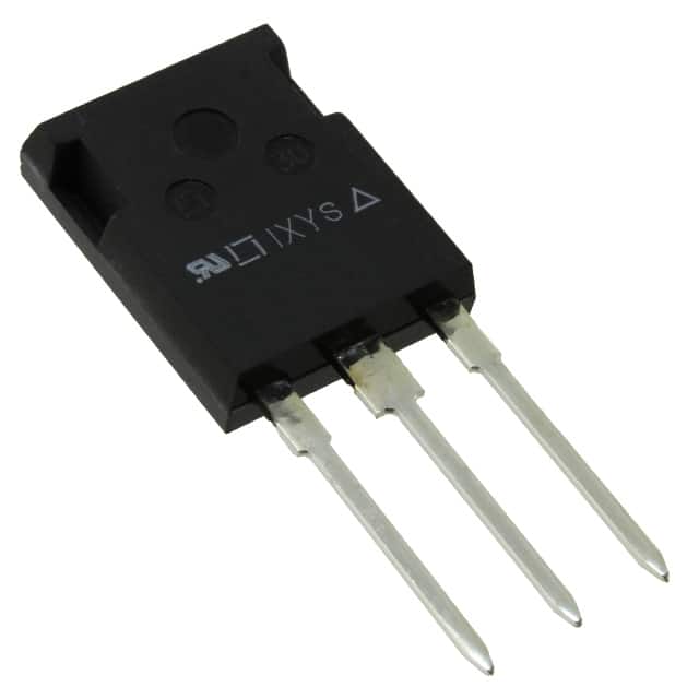
- Package: TO-247
- Essence: Insulated Gate Bipolar Transistor (IGBT)
- Packaging/Quantity: Single unit packaging
Specifications
- Voltage Rating: 600V
- Current Rating: 40A
- Switching Frequency: Up to 20kHz
- Operating Temperature: -55°C to 150°C
- Gate-Emitter Voltage: ±20V
Detailed Pin Configuration
The IXGR40N60C2G1 features a standard TO-247 pin configuration with three pins: collector, gate, and emitter.
Functional Features
- High voltage capability
- Low saturation voltage
- Fast switching speed
- Overcurrent protection
Advantages and Disadvantages
Advantages: - High power handling capability - Low on-state voltage drop - Fast switching times
Disadvantages: - High switching losses - Sensitivity to overvoltage conditions
Working Principles
The IXGR40N60C2G1 operates based on the principles of insulated gate bipolar transistor technology. When a positive voltage is applied to the gate terminal, it allows current to flow between the collector and emitter terminals, enabling high-power switching applications.
Detailed Application Field Plans
This IGBT is suitable for various high-power applications including: - Motor drives - Uninterruptible power supplies (UPS) - Renewable energy systems - Industrial welding equipment
Detailed and Complete Alternative Models
- IXGR30N60C2D1: Lower current rating (30A) version of the same IGBT
- IXGR50N60C2: Higher current rating (50A) version of the same IGBT
- IXGH40N60C2D1: Higher voltage rating (1200V) version of the same IGBT
This comprehensive entry provides an in-depth understanding of the IXGR40N60C2G1, covering its specifications, functional features, application field plans, and alternative models, making it a valuable resource for engineers and enthusiasts in the power semiconductor industry.
Lista 10 Vanliga frågor och svar relaterade till tillämpningen av IXGR40N60C2G1 i tekniska lösningar
What is the maximum voltage rating of IXGR40N60C2G1?
- The maximum voltage rating of IXGR40N60C2G1 is 600V.
What is the continuous current rating of IXGR40N60C2G1?
- The continuous current rating of IXGR40N60C2G1 is 40A.
Can IXGR40N60C2G1 be used in high-frequency applications?
- Yes, IXGR40N60C2G1 is suitable for high-frequency applications due to its fast switching characteristics.
What is the typical on-state voltage drop of IXGR40N60C2G1?
- The typical on-state voltage drop of IXGR40N60C2G1 is around 1.8V at 25°C.
Is IXGR40N60C2G1 suitable for motor drive applications?
- Yes, IXGR40N60C2G1 can be used in motor drive applications due to its high current capability and low on-state voltage.
Does IXGR40N60C2G1 require a heat sink for thermal management?
- Yes, it is recommended to use a heat sink for efficient thermal management, especially in high-power applications.
What is the maximum junction temperature of IXGR40N60C2G1?
- The maximum junction temperature of IXGR40N60C2G1 is 150°C.
Can IXGR40N60C2G1 be used in parallel to increase current handling capacity?
- Yes, IXGR40N60C2G1 can be used in parallel to increase the overall current handling capacity in a circuit.
What are the typical applications of IXGR40N60C2G1?
- Typical applications of IXGR40N60C2G1 include power supplies, motor drives, UPS systems, and welding equipment.
Is IXGR40N60C2G1 RoHS compliant?
- Yes, IXGR40N60C2G1 is RoHS compliant, making it suitable for environmentally friendly designs.