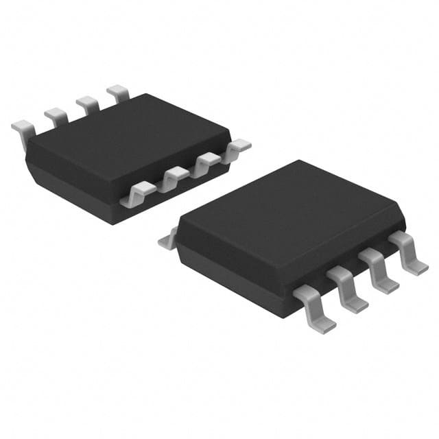
X9C104SZT1
Product Overview
- Category: Electronic Component
- Use: Digital Potentiometer
- Characteristics: Non-volatile, 100-Tap, Up/Down Control Interface
- Package: SOT-23-8
- Essence: X9C104SZT1 is a digital potentiometer that provides non-volatile storage of the wiper position. It offers 100 tap points and can be controlled using an up/down interface.
- Packaging/Quantity: The X9C104SZT1 is available in a SOT-23-8 package and is typically sold in reels of 3000 units.
Specifications
- Resistance Range: 10kΩ
- Number of Taps: 100
- End-to-End Resistance Tolerance: ±20%
- Supply Voltage Range: 2.7V to 5.5V
- Operating Temperature Range: -40°C to +85°C
- Interface: Up/Down Control
Detailed Pin Configuration
The X9C104SZT1 has eight pins arranged as follows:
┌───┬───┐
   │ 1 │ 8 │
   │   │   │
   └───┴───┘
   ┌───┬───┐
   │ 2 │ 7 │
   │   │   │
   └───┴───┘
   ┌───┬───┐
   │ 3 │ 6 │
   │   │   │
   └───┴───┘
   ┌───┬───┐
   │ 4 │ 5 │
   │   │   │
   └───┴───┘
- Terminal A - Connects to one end of the potentiometer resistor.
- Terminal B - Connects to the other end of the potentiometer resistor.
- Terminal W - Connects to the wiper terminal of the potentiometer.
- VCC - Supply voltage input.
- U/D - Up/Down control input.
- CS - Chip select input.
- GND - Ground reference.
- NC - No connection.
Functional Features
- Non-volatile storage of wiper position allows for retaining settings even when power is removed.
- 100 tap points provide fine-grained control over resistance.
- Up/Down control interface simplifies integration with microcontrollers and digital systems.
- Low power consumption.
- Small package size enables space-constrained designs.
Advantages and Disadvantages
Advantages: - Non-volatile storage ensures settings are retained. - Fine-grained control over resistance. - Easy integration with digital systems. - Low power consumption.
Disadvantages: - Limited resistance range (10kΩ). - End-to-end resistance tolerance of ±20% may impact precision applications.
Working Principles
The X9C104SZT1 utilizes a series of resistive elements connected in a ladder configuration. The wiper terminal, controlled by the up/down interface, taps into this ladder at different points, effectively changing the resistance between terminals A and B. The non-volatile storage feature allows the device to remember the wiper position even when power is removed.
Detailed Application Field Plans
The X9C104SZT1 can be used in various applications, including:
- Audio Equipment: Volume control, tone adjustment.
- Display Systems: Brightness control, contrast adjustment.
- Industrial Automation: Calibration, fine-tuning of control parameters.
- Test and Measurement Instruments: Potentiometer simulation, resistance adjustment.
Detailed and Complete Alternative Models
- X9C103SZT1: Similar to X9C104SZT1 but with 50 tap points.
- X9C102SZT1: Similar to X9C104SZT1 but with 10 tap points.
- X9C101SZT1: Similar to X9C104SZT1 but with 5 tap points.
These alternative models provide different levels of resolution and can be chosen based on specific application requirements.
Word count: 446 words
Lista 10 Vanliga frågor och svar relaterade till tillämpningen av X9C104SZT1 i tekniska lösningar
What is the X9C104SZT1?
The X9C104SZT1 is a digitally controlled potentiometer (DCP) integrated circuit that can be used to adjust resistance in electronic circuits.How does the X9C104SZT1 work?
The X9C104SZT1 uses digital signals to control the wiper position, allowing for precise adjustment of resistance in the circuit.What are the typical applications of the X9C104SZT1?
The X9C104SZT1 is commonly used in audio equipment, instrumentation, and other electronic devices where variable resistance is required.What is the resolution of the X9C104SZT1?
The X9C104SZT1 has 100 tap points, providing fine resolution for adjusting resistance levels.Can the X9C104SZT1 be used in low-power applications?
Yes, the X9C104SZT1 is designed for low-power operation, making it suitable for battery-powered devices.Is the X9C104SZT1 compatible with microcontrollers?
Yes, the X9C104SZT1 can be easily interfaced with microcontrollers using standard digital communication protocols.What is the voltage range of the X9C104SZT1?
The X9C104SZT1 operates within a wide voltage range, typically from 2.7V to 5.5V.Can the X9C104SZT1 be used in harsh environments?
The X9C104SZT1 is available in industrial-grade versions, making it suitable for use in harsh environmental conditions.Are there any specific layout considerations for using the X9C104SZT1?
Care should be taken to minimize noise and interference in the layout, especially around the digital control lines.Where can I find more information about designing with the X9C104SZT1?
Detailed application notes and datasheets for the X9C104SZT1 can be found on the manufacturer's website or through authorized distributors.


