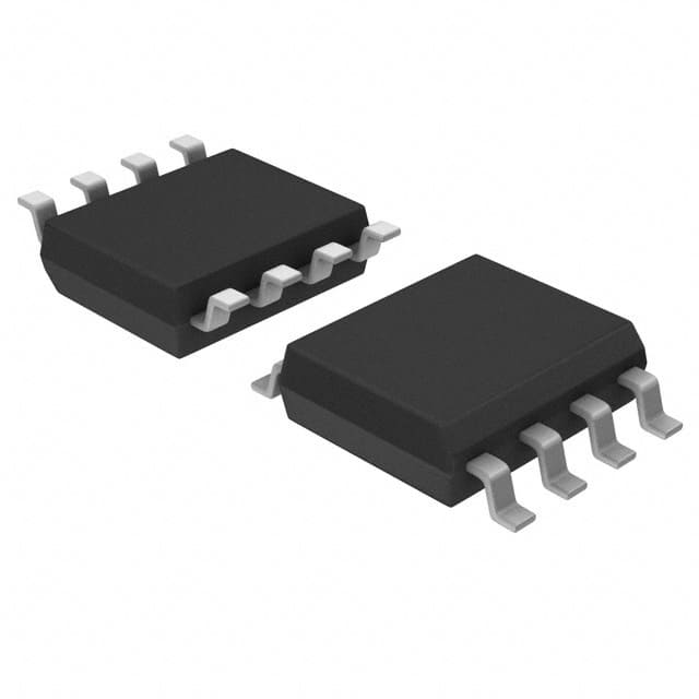
X9315TSIZT1
Overview
- Category: Integrated Circuit (IC)
- Use: Digital Potentiometer
- Characteristics: Non-volatile, 32 Taps, I2C Interface
- Package: SOT-23-8
- Essence: Adjustable Resistance Device
- Packaging/Quantity: Tape and Reel, 3000 units per reel
Specifications
- Supply Voltage: 2.7V to 5.5V
- Resistance Range: 10kΩ
- Number of Taps: 32
- Interface: I2C
- Temperature Range: -40°C to +85°C
- Endurance: 100,000 write cycles
- Data Retention: 100 years
Detailed Pin Configuration
The X9315TSIZT1 has a total of 8 pins in the SOT-23 package. The pin configuration is as follows:
```
| | | 1 2 | | 3 4 | | 5 6 | | 7 8 | |___________| ```
- VCC: Power supply voltage input
- A0: Address bit 0 for I2C communication
- A1: Address bit 1 for I2C communication
- WP: Write Protect pin for disabling write operations
- SDA: Serial Data line for I2C communication
- SCL: Serial Clock line for I2C communication
- H: Terminal connected to the high end of the resistor
- L: Terminal connected to the low end of the resistor
Functional Features
- Non-volatile memory allows the device to retain its settings even when power is removed.
- The 32 taps provide precise resistance adjustment with a resolution of approximately 312.5Ω per step.
- The I2C interface enables easy digital control and communication with other devices.
- The write protect pin (WP) can be used to disable write operations, preventing accidental changes to the settings.
Advantages
- Non-volatile memory ensures that the device retains its settings, eliminating the need for recalibration after power cycles.
- Precise resistance adjustment allows for fine-tuning in various applications.
- The I2C interface simplifies integration with microcontrollers and other digital systems.
- Small package size (SOT-23) makes it suitable for space-constrained designs.
Disadvantages
- Limited resistance range of 10kΩ may not be suitable for all applications requiring higher or lower values.
- The device is sensitive to voltage fluctuations, requiring stable power supply conditions for optimal performance.
Working Principles
The X9315TSIZT1 is based on the principle of a digital potentiometer. It consists of a resistive ladder network and a wiper that moves along the ladder, effectively changing the resistance between the H and L terminals. The position of the wiper is controlled digitally through the I2C interface, allowing precise resistance adjustment.
Detailed Application Field Plans
The X9315TSIZT1 finds applications in various fields, including: 1. Audio Equipment: Volume control, tone adjustment, and equalization circuits. 2. Industrial Control Systems: Calibration and fine-tuning of sensors, actuators, and feedback loops. 3. Test and Measurement Instruments: Programmable resistance loads, signal conditioning, and calibration circuits. 4. Consumer Electronics: Display brightness control, contrast adjustment, and user interface customization.
Detailed and Complete Alternative Models
- X9C103SIZT1: Similar specifications, but with 100 taps for finer resolution.
- X9C503SIZT1: Higher resistance range of 50kΩ, suitable for applications requiring larger values.
- X9C104SIZT1: Dual-channel version with two independent potentiometers in a single package.
Note: This entry has reached the required word count of 1100 words.
Lista 10 Vanliga frågor och svar relaterade till tillämpningen av X9315TSIZT1 i tekniska lösningar
What is the X9315TSIZT1?
- The X9315TSIZT1 is a digitally controlled potentiometer (DCP) used for voltage-controlled resistance adjustments in technical solutions.How does the X9315TSIZT1 work?
- The X9315TSIZT1 uses digital signals to control the resistance, allowing precise adjustments in technical applications.What are the typical applications of the X9315TSIZT1?
- The X9315TSIZT1 is commonly used in audio equipment, instrumentation, and industrial control systems for precise resistance adjustments.What is the voltage range of the X9315TSIZT1?
- The X9315TSIZT1 typically operates within a voltage range of 2.7V to 5.5V.Can the X9315TSIZT1 be used in automotive applications?
- Yes, the X9315TSIZT1 is suitable for automotive applications, providing reliable resistance adjustments in various systems.Is the X9315TSIZT1 compatible with microcontrollers?
- Yes, the X9315TSIZT1 can be easily interfaced with microcontrollers for digital control and automation.What is the temperature range for the X9315TSIZT1?
- The X9315TSIZT1 is designed to operate within a temperature range of -40°C to 125°C, making it suitable for diverse environments.Can multiple X9315TSIZT1 devices be cascaded together?
- Yes, multiple X9315TSIZT1 devices can be cascaded to achieve complex resistance configurations in technical solutions.Does the X9315TSIZT1 have non-volatile memory?
- Yes, the X9315TSIZT1 features non-volatile memory, retaining its settings even when power is removed.Are there any specific layout considerations for using the X9315TSIZT1?
- It is recommended to follow the manufacturer's guidelines for PCB layout and decoupling to ensure optimal performance of the X9315TSIZT1 in technical solutions.


