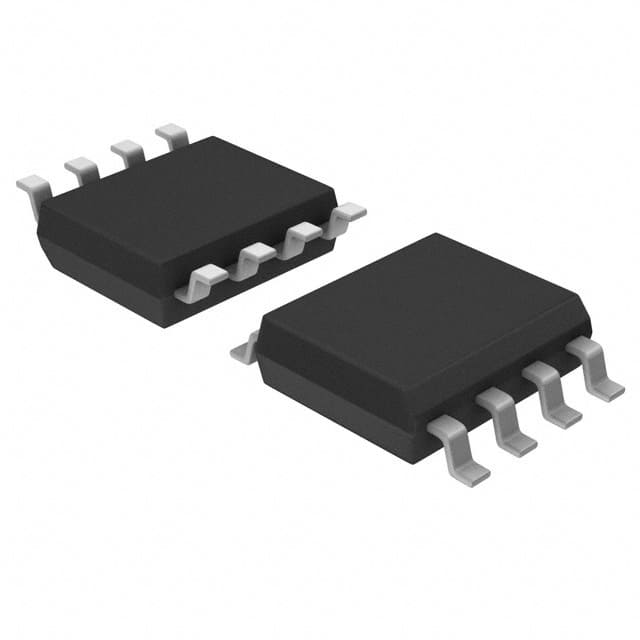
X9313ZSZT1
Product Overview
- Category: Integrated Circuit (IC)
- Use: Digital Potentiometer
- Characteristics:
- Low power consumption
- High resolution
- Non-volatile memory
- Small package size
- Package: SOT-23-8
- Essence: X9313ZSZT1 is a digital potentiometer IC that provides variable resistance in electronic circuits. It offers precise control over resistance values and can be used in various applications.
- Packaging/Quantity: Available in tape and reel packaging, with 3000 units per reel.
Specifications
- Resolution: 256 taps
- Resistance Range: 10kΩ
- Supply Voltage: 2.7V to 5.5V
- Operating Temperature Range: -40°C to +85°C
- End-to-End Resistance Tolerance: ±20%
- Total Resistance Tolerance: ±30%
Detailed Pin Configuration
The X9313ZSZT1 IC has the following pin configuration:
```
| | --| VCC A |-- VCC (Power Supply) --| CS B |-- CS (Chip Select) --| U/D W |-- U/D (Up/Down Control) --| GND H |-- GND (Ground) |___________| ```
Functional Features
- Non-volatile Memory: The X9313ZSZT1 retains its settings even when power is disconnected, allowing for easy restoration of previous configurations.
- Up/Down Control: The U/D pin enables the user to increment or decrement the resistance value digitally.
- Low Power Consumption: This IC consumes minimal power, making it suitable for battery-powered devices.
- High Resolution: With 256 taps, the X9313ZSZT1 provides fine-grained control over resistance values.
Advantages and Disadvantages
Advantages: - Non-volatile memory ensures settings are retained - High resolution allows precise resistance control - Low power consumption extends battery life - Small package size saves board space
Disadvantages: - Limited resistance range (10kΩ) - End-to-end resistance tolerance of ±20% may not be suitable for highly precise applications
Working Principles
The X9313ZSZT1 is based on the concept of a digital potentiometer. It consists of a series of resistive elements connected in a ladder-like configuration. By digitally controlling the taps along this ladder, the effective resistance between two terminals can be adjusted.
When the U/D pin receives an increment or decrement signal, the IC adjusts the tap position accordingly, changing the resistance value. The non-volatile memory ensures that the resistance setting is preserved even when power is removed.
Detailed Application Field Plans
The X9313ZSZT1 finds applications in various fields, including:
- Audio Equipment: Used to control volume levels and tone adjustments.
- Industrial Automation: Provides adjustable resistance for calibration and control purposes.
- Test and Measurement Instruments: Enables precise resistance simulation and adjustment.
- Communication Systems: Used in signal conditioning circuits and impedance matching networks.
- Automotive Electronics: Provides variable resistance for sensor calibration and control circuits.
Detailed and Complete Alternative Models
- X9C103S: 100Ω, 64 taps, SOIC-8 package
- MCP4017T: 10kΩ, 129 taps, SOT-23-6 package
- AD8403ARZ1: 1kΩ, 256 taps, TSSOP-16 package
- MAX5481EUD+: 50kΩ, 256 taps, µMAX-8 package
- CAT5114YI-50-T3: 50Ω, 256 taps, SOT-23-8 package
These alternative models offer different resistance ranges, tap resolutions, and package options to suit various application requirements.
Word count: 366 words
Lista 10 Vanliga frågor och svar relaterade till tillämpningen av X9313ZSZT1 i tekniska lösningar
Sure! Here are 10 common questions and answers related to the application of X9313ZSZT1 in technical solutions:
Q1: What is the X9313ZSZT1? A1: The X9313ZSZT1 is a digital potentiometer, also known as a digital variable resistor, that can be used in various electronic circuits.
Q2: What is the purpose of using the X9313ZSZT1 in technical solutions? A2: The X9313ZSZT1 can be used to control resistance digitally, allowing for precise adjustment of circuit parameters such as volume control, brightness control, or motor speed control.
Q3: How does the X9313ZSZT1 work? A3: The X9313ZSZT1 consists of a series of resistive elements and switches. By toggling the switches, the effective resistance between two terminals can be adjusted digitally.
Q4: What is the voltage range supported by the X9313ZSZT1? A4: The X9313ZSZT1 supports a voltage range of 2.7V to 5.5V.
Q5: Can the X9313ZSZT1 be used in both analog and digital circuits? A5: Yes, the X9313ZSZT1 can be used in both analog and digital circuits, depending on the specific application requirements.
Q6: How many resistance taps does the X9313ZSZT1 have? A6: The X9313ZSZT1 has 32 resistance taps, allowing for fine-grained adjustment of resistance levels.
Q7: Is the X9313ZSZT1 compatible with microcontrollers? A7: Yes, the X9313ZSZT1 can be easily interfaced with microcontrollers using standard digital communication protocols such as I2C.
Q8: Can the X9313ZSZT1 be used in automotive applications? A8: Yes, the X9313ZSZT1 is suitable for automotive applications, as it can withstand high temperatures and has a wide operating voltage range.
Q9: What is the typical power consumption of the X9313ZSZT1? A9: The X9313ZSZT1 has a low power consumption, typically around 1mW.
Q10: Are there any specific precautions to consider when using the X9313ZSZT1? A10: It is important to ensure that the maximum voltage and current ratings of the X9313ZSZT1 are not exceeded. Additionally, proper decoupling capacitors should be used to minimize noise and ensure stable operation.
Please note that these answers are general and may vary depending on the specific application and requirements.


