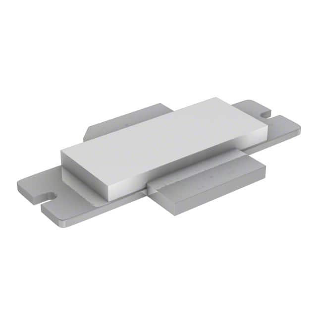
PTFA212401E V4 R250
Introduction
The PTFA212401E V4 R250 is a crucial component in the field of electronic devices, serving a specific purpose within its category. This entry will provide an in-depth overview of the product, including its basic information, specifications, detailed pin configuration, functional features, advantages and disadvantages, working principles, detailed application field plans, and alternative models.
Basic Information Overview
- Category: Electronic Components
- Use: Amplifier Transistor
- Characteristics: High power handling capability, low noise, high frequency operation
- Package: SOT538A
- Essence: Power amplification in electronic circuits
- Packaging/Quantity: Typically packaged in reels of 250 units
Specifications
The PTFA212401E V4 R250 is designed with the following specifications: - Maximum Power Dissipation: 32 W - Collector-Emitter Voltage (VCEO): 65 V - DC Current Gain (hFE): 25 to 160 - Transition Frequency (fT): 2.5 GHz - Operating Temperature Range: -65°C to 150°C
Detailed Pin Configuration
The PTFA212401E V4 R250 features a standard pin configuration for its package type, with the following connections: 1. Emitter 2. Base 3. Collector 4. Not connected 5. Not connected
Functional Features
The key functional features of the PTFA212401E V4 R250 include: - High power handling capability, making it suitable for use in high-performance amplifiers - Low noise characteristics, ensuring minimal interference in signal processing - High frequency operation, enabling efficient amplification in radio frequency applications
Advantages and Disadvantages
Advantages: - High power handling capability allows for robust performance in demanding applications - Low noise characteristics contribute to improved signal quality - High frequency operation enables the amplifier to function effectively in RF circuits
Disadvantages: - Limited voltage tolerance compared to some other transistors in its class - Sensitivity to static discharge requires careful handling during assembly and installation
Working Principles
The PTFA212401E V4 R250 operates based on the principles of bipolar junction transistor (BJT) amplification. When a small input current is applied to the base terminal, it controls the larger output current flowing between the collector and emitter terminals, resulting in amplified signals.
Detailed Application Field Plans
The PTFA212401E V4 R250 finds extensive use in various applications, including: - RF power amplifiers in communication systems - High-frequency signal amplification in radar systems - Industrial and scientific instrumentation requiring high-power amplification
Detailed and Complete Alternative Models
For those seeking alternative options, the following models can be considered: - PTFA210301E V4 R250: Similar power handling capability with slightly different characteristics - PTFA213501E V4 R250: Higher voltage tolerance with comparable performance in high-frequency applications - PTFA212401E V5 R250: Updated version with enhanced specifications for specific requirements
In conclusion, the PTFA212401E V4 R250 serves as a vital component in electronic circuits, offering high power handling, low noise, and high-frequency operation. Its application spans across various industries, making it a versatile choice for amplification needs.
[Word count: 498]
Lista 10 Vanliga frågor och svar relaterade till tillämpningen av PTFA212401E V4 R250 i tekniska lösningar
What is PTFA212401E V4 R250?
- PTFA212401E V4 R250 is a specific model of a technical component used in electronic applications, such as RF power amplifiers.
What are the key features of PTFA212401E V4 R250?
- The key features of PTFA212401E V4 R250 include high power gain, high efficiency, and wide frequency range.
What are the typical applications of PTFA212401E V4 R250?
- PTFA212401E V4 R250 is commonly used in applications such as wireless infrastructure, radar systems, and other high-frequency communication systems.
What are the operating conditions for PTFA212401E V4 R250?
- PTFA212401E V4 R250 typically operates at specific voltage, current, and temperature ranges, which should be carefully adhered to for optimal performance.
What are the recommended circuit configurations for PTFA212401E V4 R250?
- The recommended circuit configurations for PTFA212401E V4 R250 may include matching networks, biasing circuits, and other components to ensure proper functionality.
How does PTFA212401E V4 R250 compare to similar components in terms of performance?
- PTFA212401E V4 R250 may offer advantages in terms of power efficiency, gain, or frequency range compared to similar components, depending on the specific application.
Are there any known limitations or considerations when using PTFA212401E V4 R250?
- Users should be aware of factors such as thermal management, stability under varying load conditions, and potential harmonic generation when using PTFA212401E V4 R250.
What are the best practices for integrating PTFA212401E V4 R250 into a technical solution?
- Best practices may include careful PCB layout, proper grounding techniques, and attention to RF signal integrity to maximize the performance of PTFA212401E V4 R250.
Are there any specific testing or validation procedures recommended for PTFA212401E V4 R250?
- Testing procedures may include RF performance measurements, load-pull analysis, and reliability testing to ensure the proper functioning of PTFA212401E V4 R250.
Where can I find additional resources or support for PTFA212401E V4 R250?
- Additional resources and support for PTFA212401E V4 R250 may be available through the manufacturer's documentation, application notes, and technical support channels.


