

IRG4PH40UPBF
Introduction
The IRG4PH40UPBF is a power semiconductor device belonging to the category of Insulated Gate Bipolar Transistors (IGBTs). This entry provides an overview of the basic information, specifications, pin configuration, functional features, advantages and disadvantages, working principles, application field plans, and alternative models of the IRG4PH40UPBF.
Basic Information Overview
- Category: Insulated Gate Bipolar Transistor (IGBT)
- Use: Power switching applications in various electronic devices and systems
- Characteristics: High voltage capability, low saturation voltage, fast switching speed
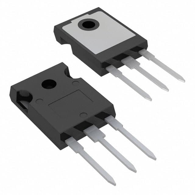
- Package: TO-247AC
- Essence: Power control and conversion
- Packaging/Quantity: Typically sold individually or in small quantities
Specifications
- Voltage Rating: 1200V
- Current Rating: 40A
- Maximum Power Dissipation: 300W
- Operating Temperature Range: -55°C to 150°C
- Gate-Emitter Voltage: ±20V
Detailed Pin Configuration
The IRG4PH40UPBF IGBT typically has the following pin configuration: 1. Collector (C) 2. Gate (G) 3. Emitter (E)
Functional Features
- High voltage capability for power applications
- Low saturation voltage for efficient power switching
- Fast switching speed for improved performance
- Robust construction for reliability in demanding environments
Advantages and Disadvantages
Advantages
- High voltage capability enables use in diverse power applications
- Low saturation voltage reduces power losses during operation
- Fast switching speed allows for efficient power control
Disadvantages
- Higher cost compared to some alternative technologies
- Sensitivity to overvoltage conditions may require additional protection circuitry
Working Principles
The IRG4PH40UPBF operates based on the principles of controlling the flow of current between the collector and emitter terminals using the gate signal. When a suitable voltage is applied to the gate terminal, it allows the IGBT to conduct current, enabling power switching and control.
Detailed Application Field Plans
The IRG4PH40UPBF finds extensive use in various power electronics applications, including: - Motor drives - Uninterruptible power supplies (UPS) - Renewable energy systems - Industrial power control systems - Electric vehicle powertrains
Detailed and Complete Alternative Models
Some alternative models to the IRG4PH40UPBF include: - IRG4BC30UD - FGA25N120ANTD - IXGH32N60BD1
In summary, the IRG4PH40UPBF is a high-voltage IGBT with fast switching characteristics, making it suitable for a wide range of power control and conversion applications.
[Word count: 398]
Lista 10 Vanliga frågor och svar relaterade till tillämpningen av IRG4PH40UPBF i tekniska lösningar
What is the maximum voltage rating of IRG4PH40UPBF?
- The maximum voltage rating of IRG4PH40UPBF is 1200V.
What is the maximum current rating of IRG4PH40UPBF?
- The maximum current rating of IRG4PH40UPBF is 55A.
What type of package does IRG4PH40UPBF come in?
- IRG4PH40UPBF comes in a TO-247AC package.
What are the typical applications for IRG4PH40UPBF?
- IRG4PH40UPBF is commonly used in applications such as motor drives, inverters, and power supplies.
What is the gate-emitter voltage (VGE) for IRG4PH40UPBF?
- The gate-emitter voltage (VGE) for IRG4PH40UPBF is typically 20V.
What is the on-state voltage drop of IRG4PH40UPBF?
- The on-state voltage drop of IRG4PH40UPBF is typically around 2.2V.
Does IRG4PH40UPBF have built-in protection features?
- Yes, IRG4PH40UPBF has built-in features such as overcurrent protection and short-circuit protection.
What is the operating temperature range for IRG4PH40UPBF?
- The operating temperature range for IRG4PH40UPBF is -55°C to 150°C.
Is IRG4PH40UPBF RoHS compliant?
- Yes, IRG4PH40UPBF is RoHS compliant.
What are some key advantages of using IRG4PH40UPBF in technical solutions?
- Some key advantages of using IRG4PH40UPBF include high voltage capability, low switching losses, and ruggedness for harsh environments.