

Encyclopedia Entry: 74SSTVF16857PAG8
Product Overview
Category
The 74SSTVF16857PAG8 belongs to the category of integrated circuits (ICs).
Use
This IC is commonly used in electronic devices for signal transmission and processing.
Characteristics
- High-speed operation
- Low power consumption
- Wide operating voltage range
- Compact size
Package
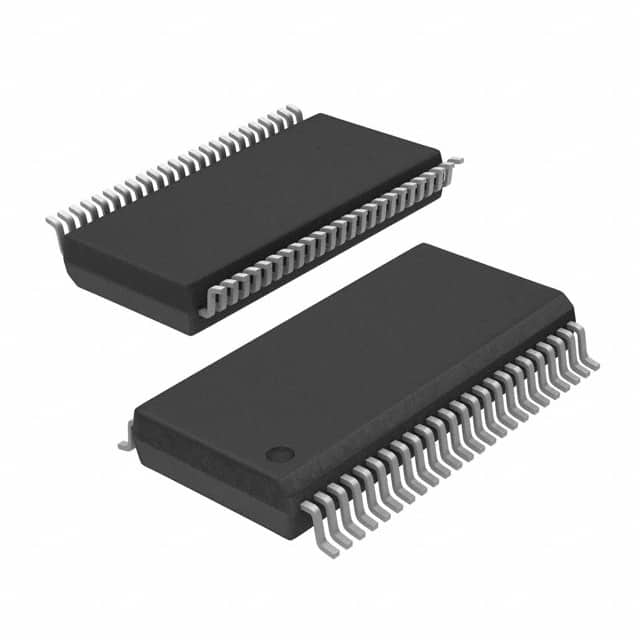
The 74SSTVF16857PAG8 is available in a small outline integrated circuit (SOIC) package.
Essence
This IC is designed to enhance signal integrity and ensure reliable data transmission in various electronic applications.
Packaging/Quantity
The 74SSTVF16857PAG8 is typically packaged in reels or tubes, with a quantity of 250 units per reel/tube.
Specifications
- Supply Voltage: 2.3V - 3.6V
- Operating Temperature Range: -40°C to +85°C
- Input/Output Type: Differential
- Number of Channels: 16
- Data Rate: Up to 1.6 Gbps
- Logic Family: SSTL_18
Detailed Pin Configuration
The 74SSTVF16857PAG8 has a total of 56 pins. The pin configuration is as follows:
- Pin 1: Channel 0 Output
- Pin 2: Channel 0 Output Bar
- Pin 3: Channel 1 Output
- Pin 4: Channel 1 Output Bar
- Pin 5: Channel 2 Output
- Pin 6: Channel 2 Output Bar
- Pin 7: Channel 3 Output
- Pin 8: Channel 3 Output Bar
- Pin 9: Channel 4 Output
- Pin 10: Channel 4 Output Bar
- Pin 11: Channel 5 Output
- Pin 12: Channel 5 Output Bar
- Pin 13: Channel 6 Output
- Pin 14: Channel 6 Output Bar
- Pin 15: Channel 7 Output
- Pin 16: Channel 7 Output Bar
- Pin 17: Channel 8 Output
- Pin 18: Channel 8 Output Bar
- Pin 19: Channel 9 Output
- Pin 20: Channel 9 Output Bar
- Pin 21: Channel 10 Output
- Pin 22: Channel 10 Output Bar
- Pin 23: Channel 11 Output
- Pin 24: Channel 11 Output Bar
- Pin 25: Channel 12 Output
- Pin 26: Channel 12 Output Bar
- Pin 27: Channel 13 Output
- Pin 28: Channel 13 Output Bar
- Pin 29: Channel 14 Output
- Pin 30: Channel 14 Output Bar
- Pin 31: Channel 15 Output
- Pin 32: Channel 15 Output Bar
- Pin 33: VDD
- Pin 34: GND
- Pin 35: Channel 0 Input
- Pin 36: Channel 0 Input Bar
- Pin 37: Channel 1 Input
- Pin 38: Channel 1 Input Bar
- Pin 39: Channel 2 Input
- Pin 40: Channel 2 Input Bar
- Pin 41: Channel 3 Input
- Pin 42: Channel 3 Input Bar
- Pin 43: Channel 4 Input
- Pin 44: Channel 4 Input Bar
- Pin 45: Channel 5 Input
- Pin 46: Channel 5 Input Bar
- Pin 47: Channel 6 Input
- Pin 48: Channel 6 Input Bar
- Pin 49: Channel 7 Input
- Pin 50: Channel 7 Input Bar
- Pin 51: Channel 8 Input
- Pin 52: Channel 8 Input Bar
- Pin 53: Channel 9 Input
- Pin 54: Channel 9 Input Bar
- Pin 55: Channel 10 Input
- Pin 56: Channel 10 Input Bar
Functional Features
- High-speed differential signal transmission
- Low voltage swing operation
- Built-in termination resistors for impedance matching
- ESD protection on inputs and outputs
- Compatible with various logic families
Advantages and Disadvantages
Advantages
- High-speed operation enables efficient data transmission
- Low power consumption contributes to energy efficiency
- Wide operating voltage range allows compatibility with different systems
- Compact size facilitates integration into space
Lista 10 Vanliga frågor och svar relaterade till tillämpningen av 74SSTVF16857PAG8 i tekniska lösningar
Sure! Here are 10 common questions and answers related to the application of 74SSTVF16857PAG8 in technical solutions:
Q: What is the 74SSTVF16857PAG8? A: The 74SSTVF16857PAG8 is a high-speed, low-power 20-bit registered buffer with 3-state outputs.
Q: What are the key features of the 74SSTVF16857PAG8? A: Some key features include wide operating voltage range, high-speed operation, low power consumption, and 3-state outputs.
Q: What is the typical application of the 74SSTVF16857PAG8? A: It is commonly used as a buffer or level shifter in various digital systems, such as data communication interfaces, memory modules, and bus drivers.
Q: What is the maximum operating frequency of the 74SSTVF16857PAG8? A: The maximum operating frequency can vary depending on the specific conditions, but it typically ranges from several hundred megahertz to a few gigahertz.
Q: Does the 74SSTVF16857PAG8 support bidirectional data transfer? A: No, the 74SSTVF16857PAG8 is a unidirectional buffer, meaning it can only drive signals in one direction.
Q: What is the power supply voltage range for the 74SSTVF16857PAG8? A: The power supply voltage range is typically between 2.3V and 3.6V.
Q: Can the 74SSTVF16857PAG8 tolerate overvoltage or undervoltage conditions? A: No, it is important to ensure that the power supply voltage remains within the specified range to prevent damage to the device.
Q: Does the 74SSTVF16857PAG8 have built-in ESD protection? A: Yes, it typically includes built-in electrostatic discharge (ESD) protection to safeguard against static electricity.
Q: What is the package type for the 74SSTVF16857PAG8? A: The 74SSTVF16857PAG8 is commonly available in a surface-mount package, such as TSSOP or QFN.
Q: Are there any recommended layout guidelines for using the 74SSTVF16857PAG8? A: Yes, it is advisable to follow the manufacturer's recommended layout guidelines, including proper decoupling capacitor placement and signal integrity considerations, to ensure optimal performance.
Please note that the answers provided here are general and may vary depending on the specific datasheet and manufacturer recommendations for the 74SSTVF16857PAG8.