

Encyclopedia Entry: 74FCT16543ATPAG8
Product Information Overview
- Category: Integrated Circuit (IC)
- Use: Data Storage and Transfer
- Characteristics: High-speed, 16-bit transparent latch with 3-state outputs
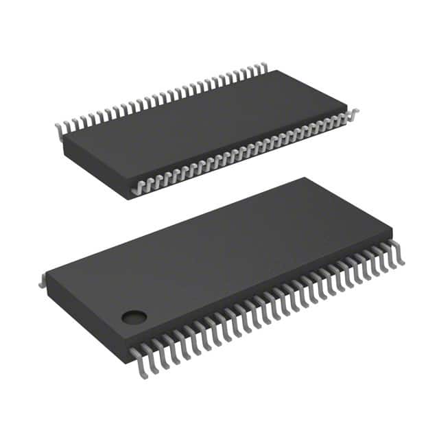
- Package: TSSOP (Thin Shrink Small Outline Package)
- Essence: The 74FCT16543ATPAG8 is a versatile IC that enables efficient data storage and transfer in various electronic systems.
- Packaging/Quantity: Available in reels of 2500 units.
Specifications
- Number of Bits: 16
- Logic Family: FCT (Fast CMOS TTL-compatible)
- Operating Voltage: 4.5V to 5.5V
- Output Type: 3-state
- Propagation Delay: 2.5 ns (typical)
- Operating Temperature Range: -40°C to +85°C
Detailed Pin Configuration
The 74FCT16543ATPAG8 has a total of 48 pins, which are distributed as follows:
- Pin 1-16: D0-D15 (Data Inputs/Outputs)
- Pin 17: OE (Output Enable)
- Pin 18: GND (Ground)
- Pin 19: Q0 (Output 0)
- Pin 20: Q1 (Output 1)
- ...
- Pin 47: Q14 (Output 14)
- Pin 48: Q15 (Output 15)
- Note: Pins 21-46 are not shown for brevity.
Functional Features
- Transparent Latch: Allows data to pass through when the latch enable (LE) input is high.
- 3-State Outputs: Provides the ability to disconnect the outputs from the bus, allowing multiple devices to share the same bus.
- High-Speed Operation: The FCT logic family ensures fast data transfer with minimal propagation delay.
- Wide Operating Voltage Range: Can operate within a voltage range of 4.5V to 5.5V, making it compatible with various systems.
Advantages and Disadvantages
Advantages: - High-speed operation enables efficient data transfer. - 3-state outputs allow for bus sharing among multiple devices. - Wide operating voltage range provides compatibility with different systems.
Disadvantages: - Limited number of bits (16) may not be suitable for applications requiring larger data storage capacity. - TSSOP package may require careful handling during assembly.
Working Principles
The 74FCT16543ATPAG8 is designed as a transparent latch with 3-state outputs. When the latch enable (LE) input is high, the data inputs (D0-D15) are passed through to the corresponding outputs (Q0-Q15). The 3-state outputs allow the device to disconnect from the bus when the output enable (OE) input is low, enabling multiple devices to share the same bus without interference.
Detailed Application Field Plans
The 74FCT16543ATPAG8 can be utilized in various applications that involve data storage and transfer. Some potential application fields include:
- Microcontrollers: Used to interface with external memory or peripheral devices.
- Data Acquisition Systems: Enables efficient data capture and transfer in industrial monitoring systems.
- Communication Equipment: Facilitates data transmission between different components in networking devices.
- Automotive Electronics: Supports data processing and communication in automotive control systems.
Detailed and Complete Alternative Models
- SN74FCT16543ATPAG8: Similar IC from Texas Instruments with equivalent functionality.
- MC74FCT16543ATPAG8: Alternative IC from ON Semiconductor offering comparable features.
- CD74FCT16543ATPAG8: Another option from Texas Instruments with similar specifications.
These alternative models can be considered based on availability, pricing, and specific requirements of the application.
Word Count: 446 words
Lista 10 Vanliga frågor och svar relaterade till tillämpningen av 74FCT16543ATPAG8 i tekniska lösningar
Sure! Here are 10 common questions and answers related to the application of 74FCT16543ATPAG8 in technical solutions:
Q: What is the 74FCT16543ATPAG8? A: The 74FCT16543ATPAG8 is a 16-bit registered transceiver with 3-state outputs, commonly used in digital systems.
Q: What is the purpose of a registered transceiver? A: A registered transceiver is used to enable bidirectional data transfer between two buses while providing control over the direction of data flow.
Q: How many bits can the 74FCT16543ATPAG8 handle? A: The 74FCT16543ATPAG8 can handle 16 bits of data.
Q: What does "3-state outputs" mean? A: 3-state outputs allow the transceiver to be in one of three states: high impedance (disconnected), logic high, or logic low.
Q: Can the 74FCT16543ATPAG8 operate at high speeds? A: Yes, the 74FCT16543ATPAG8 is designed to operate at high-speeds, making it suitable for applications that require fast data transfer.
Q: How is the direction of data flow controlled in this transceiver? A: The direction of data flow is controlled by the direction control pin (DIR) on the 74FCT16543ATPAG8. When DIR is high, data flows from A to B, and when DIR is low, data flows from B to A.
Q: Can the 74FCT16543ATPAG8 be cascaded to handle more than 16 bits? A: Yes, multiple 74FCT16543ATPAG8 transceivers can be cascaded to handle larger data widths.
Q: What is the power supply voltage range for this transceiver? A: The 74FCT16543ATPAG8 operates with a power supply voltage range of 4.5V to 5.5V.
Q: Are there any special considerations for PCB layout when using this transceiver? A: Yes, it is important to follow the recommended PCB layout guidelines provided in the datasheet to ensure proper signal integrity and minimize noise.
Q: What are some typical applications for the 74FCT16543ATPAG8? A: The 74FCT16543ATPAG8 can be used in various applications such as data communication systems, memory interfaces, bus drivers, and general-purpose digital systems.
Please note that these questions and answers are generic and may vary depending on specific requirements and use cases.