

Encyclopedia Entry: 74FCT164245TPAG8
Product Overview
Category
The 74FCT164245TPAG8 belongs to the category of integrated circuits (ICs), specifically a type of digital logic level shifter.
Use
This IC is commonly used for voltage level shifting in digital systems. It allows for seamless communication between devices operating at different voltage levels.
Characteristics
- Voltage level shifting capability
- Bidirectional data transmission
- High-speed operation
- Low power consumption
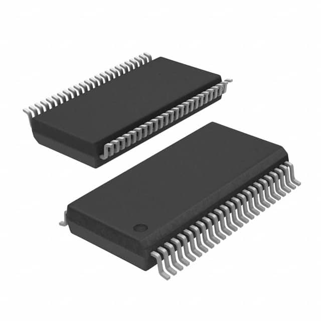
Package
The 74FCT164245TPAG8 is available in a TSSOP (Thin Shrink Small Outline Package) package. This package offers a compact size and ease of integration into electronic circuits.
Essence
The essence of this product lies in its ability to enable reliable data transfer between devices with incompatible voltage levels, ensuring compatibility and smooth operation of digital systems.
Packaging/Quantity
The 74FCT164245TPAG8 is typically packaged in reels or tubes, containing a specific quantity of ICs per package. The exact packaging and quantity may vary depending on the supplier.
Specifications
- Supply Voltage: 2.0V - 5.5V
- Logic Family: FCT
- Number of Channels: 16
- Data Direction: Bidirectional
- Maximum Data Rate: X Mbps
- Operating Temperature Range: -40°C to +85°C
Detailed Pin Configuration
The 74FCT164245TPAG8 has a total of 48 pins, which are assigned specific functions as follows:
- Pin 1: GND (Ground)
- Pin 2: A1 (Data Input/Output)
- Pin 3: B1 (Data Input/Output)
- Pin 4: A2 (Data Input/Output)
- Pin 5: B2 (Data Input/Output)
- Pin 6: A3 (Data Input/Output)
- Pin 7: B3 (Data Input/Output)
- Pin 8: A4 (Data Input/Output)
- Pin 9: B4 (Data Input/Output)
- Pin 10: A5 (Data Input/Output)
- Pin 11: B5 (Data Input/Output)
- Pin 12: A6 (Data Input/Output)
- Pin 13: B6 (Data Input/Output)
- Pin 14: A7 (Data Input/Output)
- Pin 15: B7 (Data Input/Output)
- Pin 16: A8 (Data Input/Output)
- Pin 17: B8 (Data Input/Output)
- Pin 18: OEAB (Output Enable Input, Active Low)
- Pin 19: DIRAB (Direction Control Input)
- Pin 20: VCC (Supply Voltage)
... (continued for remaining pins)
Functional Features
- Bidirectional voltage level shifting
- Automatic direction control based on DIRAB input
- Output enable control for tri-state operation
- High-speed data transmission
- Robust performance across varying supply voltages
Advantages and Disadvantages
Advantages
- Enables seamless communication between devices with different voltage levels
- Supports bidirectional data transmission
- High-speed operation allows for efficient data transfer
- Low power consumption contributes to energy efficiency
Disadvantages
- May require additional circuitry for voltage translation in complex systems
- Limited maximum data rate compared to some specialized level shifters
Working Principles
The 74FCT164245TPAG8 operates by receiving data inputs from one set of devices operating at a specific voltage level and translating them to another voltage level compatible with a different set of devices. The direction control input (DIRAB) determines the data flow direction, while the output enable input (OEAB) allows for tri-state operation when disabled.
Detailed Application Field Plans
The 74FCT164245TPAG8 finds applications in various digital systems where voltage level shifting is required. Some common application fields include:
- Microcontroller interfacing
- Communication protocols conversion
- Memory interfacing
- Sensor interfaces
- Industrial automation systems
Detailed and Complete Alternative Models
- 74HC164245: Similar functionality, but operates at a different voltage range (2.0V - 6.0V)
- SN74LVCH164245A: Low-voltage version with improved power efficiency
- CD74HCT164245: High-speed CMOS logic family alternative
These alternative models offer similar voltage level shifting capabilities with slight variations in specifications and performance characteristics.
Word count: 570 words
Lista 10 Vanliga frågor och svar relaterade till tillämpningen av 74FCT164245TPAG8 i tekniska lösningar
Sure! Here are 10 common questions and answers related to the application of 74FCT164245TPAG8 in technical solutions:
Q: What is the 74FCT164245TPAG8? A: The 74FCT164245TPAG8 is a 16-bit bidirectional transceiver with 3-state outputs, commonly used for data transfer between different logic levels or voltage domains.
Q: What is the maximum operating voltage for the 74FCT164245TPAG8? A: The maximum operating voltage for the 74FCT164245TPAG8 is typically 5.5V.
Q: Can the 74FCT164245TPAG8 be used for level shifting between different voltage domains? A: Yes, the 74FCT164245TPAG8 can be used for level shifting as it supports bidirectional data transfer between different voltage domains.
Q: What is the maximum data transfer rate supported by the 74FCT164245TPAG8? A: The maximum data transfer rate supported by the 74FCT164245TPAG8 is typically around 200 MHz.
Q: Does the 74FCT164245TPAG8 have built-in protection against overvoltage or ESD events? A: Yes, the 74FCT164245TPAG8 typically includes built-in protection features like ESD diodes to protect against overvoltage and electrostatic discharge events.
Q: Can the 74FCT164245TPAG8 be used in bus applications? A: Yes, the 74FCT164245TPAG8 is commonly used in bus applications where bidirectional data transfer is required.
Q: What is the power supply voltage range for the 74FCT164245TPAG8? A: The power supply voltage range for the 74FCT164245TPAG8 is typically between 4.5V and 5.5V.
Q: Does the 74FCT164245TPAG8 support hot-swapping of devices? A: No, the 74FCT164245TPAG8 does not support hot-swapping as it lacks specific features like bus hold or hot-insertion capability.
Q: Can the 74FCT164245TPAG8 be used in high-speed data communication applications? A: Yes, the 74FCT164245TPAG8 can be used in high-speed data communication applications due to its fast switching speed and low propagation delay.
Q: Are there any specific layout considerations when using the 74FCT164245TPAG8? A: Yes, it is recommended to follow proper PCB layout guidelines, such as minimizing trace lengths, reducing noise coupling, and providing adequate decoupling capacitors near the power supply pins, to ensure optimal performance of the 74FCT164245TPAG8.
Please note that the answers provided here are general and may vary depending on the specific datasheet and manufacturer's recommendations for the 74FCT164245TPAG8.