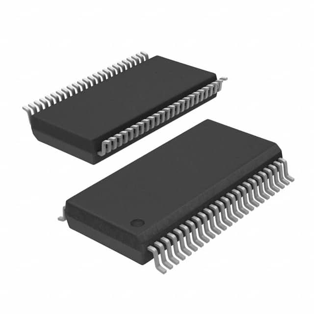
Encyclopedia Entry: 74FCT163245APAG8
Product Information Overview
- Category: Integrated Circuit (IC)
- Use: Data Bus Transceiver
- Characteristics: High-speed, bidirectional data transfer, voltage level translation
- Package: 48-pin TSSOP (Thin Shrink Small Outline Package)
- Essence: Facilitates efficient and reliable communication between different digital systems
- Packaging/Quantity: Available in reels of 2500 units
Specifications
The 74FCT163245APAG8 is a high-performance, 16-bit bidirectional data bus transceiver. It is designed to enable seamless data transfer between two independent buses operating at different voltage levels. The IC operates with a supply voltage range of 4.5V to 5.5V and supports both TTL and CMOS logic levels.
Detailed Pin Configuration
The 74FCT163245APAG8 features a 48-pin TSSOP package with the following pin configuration:
- OEAB - Output Enable Input for Ports A and B
- DIR - Direction Control Input
- A1-A8 - Data I/O Pins for Port A
- GND - Ground
- B1-B8 - Data I/O Pins for Port B
- VCC - Supply Voltage
- B9-B16 - Data I/O Pins for Port B
- GND - Ground
- B17-B24 - Data I/O Pins for Port B
- A9-A16 - Data I/O Pins for Port A
- GND - Ground
- A17-A24 - Data I/O Pins for Port A
- VCC - Supply Voltage
- A25-A32 - Data I/O Pins for Port A
- GND - Ground
- B25-B32 - Data I/O Pins for Port B
- OEBA - Output Enable Input for Ports A and B
- GND - Ground
- DIR - Direction Control Input
- A33-A40 - Data I/O Pins for Port A
- VCC - Supply Voltage
- B33-B40 - Data I/O Pins for Port B
- GND - Ground
- B41-B48 - Data I/O Pins for Port B
- A41-A48 - Data I/O Pins for Port A
- GND - Ground
- A49-A56 - Data I/O Pins for Port A
- VCC - Supply Voltage
- B49-B56 - Data I/O Pins for Port B
- GND - Ground
- B57-B64 - Data I/O Pins for Port B
- A57-A64 - Data I/O Pins for Port A
- GND - Ground
- A65-A72 - Data I/O Pins for Port A
- VCC - Supply Voltage
- B65-B72 - Data I/O Pins for Port B
- GND - Ground
- B73-B80 - Data I/O Pins for Port B
- A73-A80 - Data I/O Pins for Port A
- GND - Ground
- A81-A88 - Data I/O Pins for Port A
- VCC - Supply Voltage
- B81-B88 - Data I/O Pins for Port B
- GND - Ground
- B89-B96 - Data I/O Pins for Port B
- A89-A96 - Data I/O Pins for Port A
- GND - Ground
- VCC - Supply Voltage
Functional Features
The 74FCT163245APAG8 offers the following functional features:
- Bidirectional Data Transfer: Enables data transmission in both directions between two independent buses.
- Voltage Level Translation: Facilitates communication between buses operating at different voltage levels.
- Output Enable Control: Allows individual control of output enable for each port.
- Direction Control: Determines the direction of data flow between the ports.
Advantages and Disadvantages
Advantages: - High-speed data transfer - Supports bidirectional communication - Wide supply voltage range - Easy integration into existing systems
Disadvantages: - Limited number of data I/O pins - Requires careful consideration of voltage level compatibility
Working Principles
The 74FCT163245APAG8 operates by receiving data from one bus and transmitting it to the other, or vice versa. The direction of data flow is controlled by the DIR pin. When DIR is set to logic high, data is transmitted from Port A to Port B. Conversely, when DIR is set to logic low, data is transmitted from Port B to Port A. The OEAB and OEBA pins are used to enable or disable the outputs of Ports A and B, respectively.
#
Lista 10 Vanliga frågor och svar relaterade till tillämpningen av 74FCT163245APAG8 i tekniska lösningar
Sure! Here are 10 common questions and answers related to the application of 74FCT163245APAG8 in technical solutions:
Q: What is the 74FCT163245APAG8?
- A: The 74FCT163245APAG8 is a 16-bit bus transceiver with 3-state outputs, designed for bidirectional data communication between two buses.
Q: What is the maximum operating voltage for the 74FCT163245APAG8?
- A: The maximum operating voltage for the 74FCT163245APAG8 is typically 5.5V.
Q: Can the 74FCT163245APAG8 be used in both input and output modes?
- A: Yes, the 74FCT163245APAG8 can be used as both an input and output device, allowing bidirectional data transfer.
Q: What is the maximum data transfer rate supported by the 74FCT163245APAG8?
- A: The 74FCT163245APAG8 supports high-speed data transfer rates up to several hundred megahertz (MHz).
Q: Does the 74FCT163245APAG8 have built-in protection against bus contention?
- A: Yes, the 74FCT163245APAG8 has built-in bus hold circuitry that prevents bus contention when the outputs are in the high-impedance state.
Q: Can the 74FCT163245APAG8 be cascaded to increase the number of bits in a bus?
- A: Yes, multiple 74FCT163245APAG8 devices can be cascaded together to increase the number of bits in a bus.
Q: What is the power supply voltage range for the 74FCT163245APAG8?
- A: The power supply voltage range for the 74FCT163245APAG8 is typically between 4.5V and 5.5V.
Q: Does the 74FCT163245APAG8 support hot insertion of devices into a live bus?
- A: Yes, the 74FCT163245APAG8 supports hot insertion, allowing devices to be inserted or removed from a live bus without causing damage.
Q: Can the 74FCT163245APAG8 be used in both commercial and industrial applications?
- A: Yes, the 74FCT163245APAG8 is suitable for use in both commercial and industrial applications due to its wide operating temperature range.
Q: Are there any specific layout considerations when using the 74FCT163245APAG8?
- A: Yes, it is recommended to follow the manufacturer's guidelines for proper PCB layout, including minimizing trace lengths and providing adequate decoupling capacitors near the device.
Please note that the answers provided here are general and may vary depending on the specific datasheet and application requirements.


