

PI6C49019AIE
Overview
- Category: Integrated Circuit
- Use: Clock Generator and Buffer
- Characteristics: Low jitter, high frequency, low power consumption
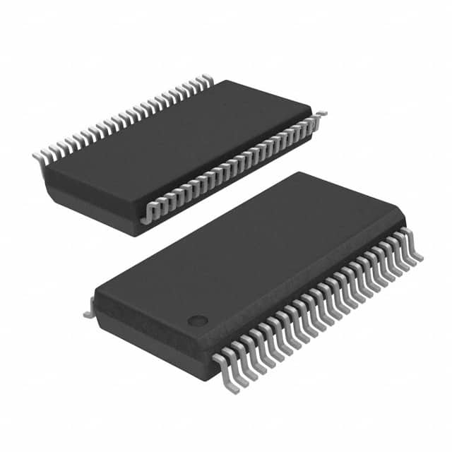
- Package: QFN (Quad Flat No-leads)
- Essence: Provides clock signals for various electronic devices
- Packaging/Quantity: Tape and Reel, 2500 pieces per reel
Specifications and Parameters
- Input Voltage Range: 1.8V to 3.3V
- Output Frequency Range: 10MHz to 400MHz
- Output Voltage Swing: 0.9V to 3.3V
- Power Consumption: 50mW
- Operating Temperature Range: -40°C to +85°C
Pin Configuration
The PI6C49019AIE has a total of 32 pins. The pin configuration is as follows:
- VDD
- GND
- CLK_OUT0
- CLK_OUT1
- CLK_OUT2
- CLK_OUT3
- CLK_OUT4
- CLK_OUT5
- CLK_OUT6
- CLK_OUT7
- CLK_OUT8
- CLK_OUT9
- CLK_OUT10
- CLK_OUT11
- CLK_OUT12
- CLK_OUT13
- CLK_OUT14
- CLK_OUT15
- CLK_OUT16
- CLK_OUT17
- CLK_OUT18
- CLK_OUT19
- CLK_OUT20
- CLK_OUT21
- CLK_OUT22
- CLK_OUT23
- CLK_OUT24
- CLK_OUT25
- CLK_OUT26
- CLK_OUT27
- CLK_OUT28
- CLK_OUT29
Functional Characteristics
- Generates up to 30 clock signals simultaneously
- Low jitter for accurate timing
- Supports high-frequency operation
- Provides stable and reliable clock signals
Advantages and Disadvantages
Advantages: - Wide input voltage range - High output frequency range - Low power consumption - Small package size
Disadvantages: - Limited number of clock outputs - Requires external components for specific applications
Applicable Range of Products
The PI6C49019AIE is suitable for various electronic devices that require multiple clock signals, such as:
- Microcontrollers
- Digital Signal Processors (DSPs)
- Field Programmable Gate Arrays (FPGAs)
- System-on-Chip (SoC) designs
Working Principles
The PI6C49019AIE operates by taking an input clock signal and generating multiple output clock signals with different frequencies. It uses a combination of dividers, phase-locked loops (PLLs), and buffers to achieve this functionality.
Detailed Application Field Plans
The PI6C49019AIE can be used in the following application fields:
- Communication Systems: Provides synchronized clock signals for data transmission and reception.
- Networking Equipment: Ensures accurate timing for routers, switches, and other network devices.
- Consumer Electronics: Enables precise timing for audio/video synchronization in TVs, DVD players, and gaming consoles.
- Industrial Automation: Facilitates synchronized operation of sensors, actuators, and control systems.
- Automotive Electronics: Provides clock signals for automotive infotainment systems, navigation devices, and driver assistance systems.
Detailed Alternative Models
Some alternative models to the PI6C49019AIE are:
- PI6C557-03QEX: Offers similar functionality with additional features.
- PI6C557-02QEX: Provides a lower output frequency range but with higher precision.
- PI6C557-01QEX: Suitable for applications with lower power requirements.
- PI6C557-00QEX: Offers a higher number of clock outputs but with a larger package size.
- PI6C557-99QEX: Provides enhanced jitter performance for critical timing applications.
5 Common Technical Questions and Answers
Q: What is the maximum output frequency of the PI6C49019AIE? A: The maximum output frequency is 400MHz.
Q: Can I use this IC with a 5V power supply? A: No, the input voltage range is limited to 1.8V to 3.3V.
Q: How many clock signals can be generated simultaneously? A: The PI6C49019AIE can generate up to 30 clock signals at the same time.
Q: Does this IC require external components for operation? A: Yes, external capacitors and resistors may be required for specific applications.
Q: What is the operating temperature range of the PI6C49019AIE? A: The IC can operate within a temperature range